

")
")
")
")
RLX COMPONENTS s.r.o. , Electronic Components Distributor.
RLX COMPONENTS s.r.o. , Electronic Components Distributor.

Pololu 5V, 600mA Step-Down Voltage Regulator D24V6F5 (POLOLU-2107)
Pololu 5V, 600mA Step-Down Voltage Regulator D24V6F5 (POLOLU-2107)
These buck (step-down) voltage regulators generate lower output voltages from input voltages as high as 42 V. They are switching regulators (also called switched-mode power supplies (SMPS) or DC-to-DC converters) and have a typical efficiency between 80% to 90%, which is much more efficient than linear voltage regulators, especially when the difference between the input and output voltage is large. This regulator is available with a fixed 3.3 V, 5 V, 9 V, or 12 V output, and two versions are available for each voltage, one with a 300 mA maximum output current (D24V3Fx) and one with a 600 mA maximum output current (D24V6Fx). Compare all products in Step-Down Voltage Regulators.
| Minimum operating voltage: | 6.0 V2 |
|---|---|
| Maximum operating voltage: | 42 V |
| Maximum output current: | 600 mA |
| Output voltage: | 5 V |
| Reverse voltage protection?: | N |
| Maximum quiescent current: | 2 mA3 |
The regulator has short-circuit protection, and thermal shutdown prevents damage from overheating. The board does not have reverse-voltage protection.
As alternatives, you might consider our newer 500 mA D24V5Fx buck regulators, which offer similar performance with much lower dropout voltages and higher efficiencies are very light loads. If you need more output current, consider our D15V35F5S3 and D15V70F5S3 3.3V/5V step-down voltage regulators, which can typically deliver a continuous 3.5 A and 7 A, respectively.
  |
 |
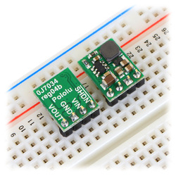
The buck regulator has four connections: shutdown (SHDN), input voltage (VIN), ground (GND), and output voltage (VOUT).
The SHDN pin can be driven low (under 0.3 V) to turn off the output and put the board into a low-power state that typically draws 20 μA, and it can be driven high (above 2.3 V) to enable the board. If you do not need to use the shutdown feature, the SHDN pin can be directly connected to VIN to permanently enable the board.You should not leave this pin disconnected as this can result in unpredictable behavior.
The input voltage, VIN, should exceed VOUT by at least the regulator’s dropout voltage (see below for graphs of dropout voltages as a function of the load), and you must ensure that noise on your input does not exceed the 42 V maximum. Additionally, please be wary of destructive LC spikes (see below for more information).
The output voltage, VOUT, is fixed and depends on the regulator version: the D24VxF3 version outputs 3.3 V, the D24VxF5 version outputs 5 V, the D24VxF9 version outputs 9 V, and the D24VxF12 version outputs 12 V.
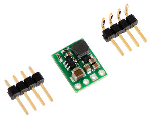
The four connections are labeled on the back side of the PCB, and they are arranged with a 0.1″ spacing along the edge of the board for compatibility with solderless breadboards, connectors, and other prototyping arrangements that use a 0.1″ grid. You can solder wires directly to the board or solder in either the 4×1straight male header strip or the 4×1 right-angle male header strip that is included.
 |
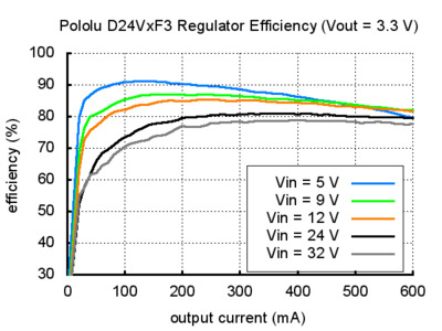
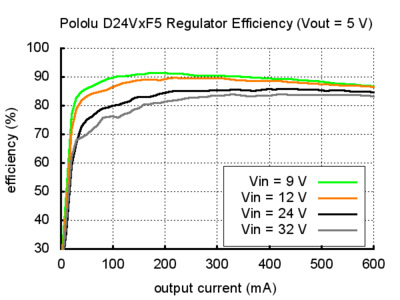
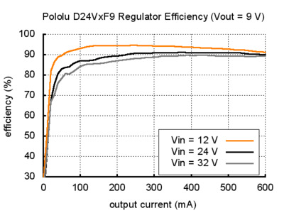
The efficiency of a voltage regulator, defined as (Power out)/(Power in), is an important measure of its performance, especially when battery life or heat are concerns. As shown in the graphs below, these switching regulators have typical efficiencies of 80% to 90%.
 |
 |
 |
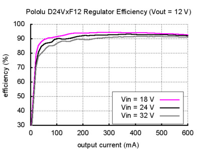 |
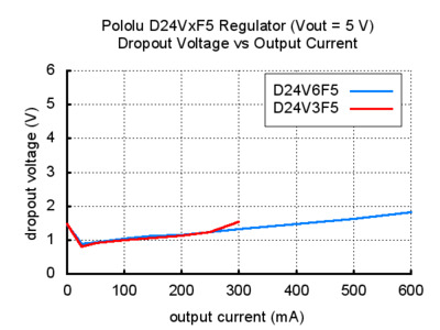
Note that the above graphs apply to both the 300 mA and 600 mA versions, which is why the x axis extends to 600 mA. You should not expect to get more than 300 mA from the 300 mA versions (D24V3Fx). These graphs and ones below do not apply to our newer 500 mA D24V5Fx buck regulators, which have different operating characteristics, including much lower dropout voltages.
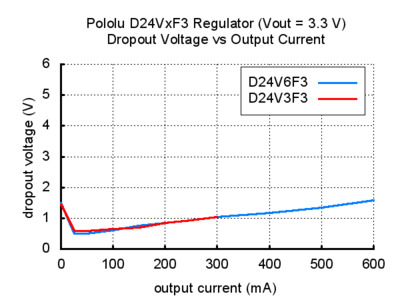
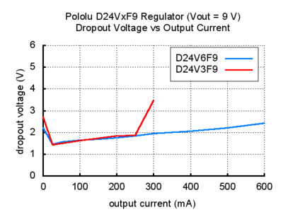
The dropout voltage of a step-down regulator is the minimum amount by which the input voltage must exceed the regulator’s target output voltage in order to ensure the target output can be achieved. For example, if a 5 V regulator has a 1 V dropout voltage, the input must be at least 6 V to ensure the output is the full 5 V. The following graphs show the dropout voltages for the eight D24V3Fx and D24V6Fx regulators as a function of the output current:
 |
 |
 |
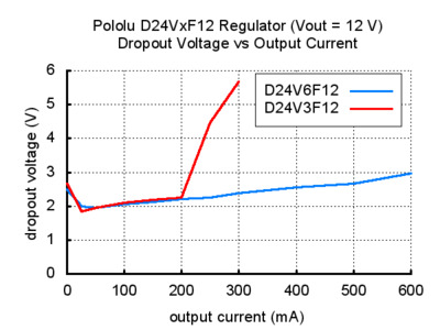 |
As you can see from the last two graphs, the dropout voltage of the low-current 9 V and 12 V versions (D24V3F9 and D24V3F12) spikes as the output current nears the 300 mA limit. For similar regulators with much lower dropout voltages, please consider our newer 500 mA D24V5Fx buck regulators.
When connecting voltage to electronic circuits, the initial rush of current can cause voltage spikes that are much higher than the input voltage. If these spikes exceed the regulator’s maximum voltage (42 V), the regulator can be destroyed. In our tests with typical power leads (~30″ test clips), input voltages above 20 V caused spikes over 42 V. If you are connecting more than 20 V or your power leads or supply has high inductance, we recommend soldering a 33μF or larger electrolytic capacitor close to the regulator between VIN and GND. The capacitor should be rated for at least 50 V.
Špecifické referencie
Pololu 5V, 600mA Step-Down Voltage Regulator D24V6F5 (POLOLU-2107)