

")
")
")
")
")
")
")
")
RLX COMPONENTS s.r.o. , Electronic Components Distributor.
RLX COMPONENTS s.r.o. , Electronic Components Distributor.

52.95 € tax excl.
CrowPanel Advanced 9inch, ESP32-P4 HMI AI Display 1024x600 IPS Touch Screen , WiFi 6 Support (DHE04209D)
CrowPanel Advanced 9inch, ESP32-P4 HMI AI Display 1024x600 IPS Touch Screen , WiFi 6 Support (DHE04209D)
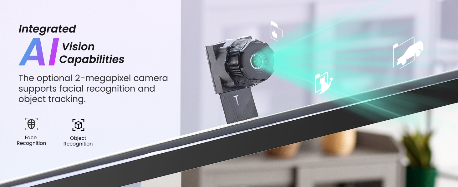
Séria CrowPanel Advance ESP32-P4 HMI je vysoko výkonný inteligentný interaktívny terminál s umelou inteligenciou určený pre náročné aplikácie. Využíva inovatívnu dvojčipovú architektúru, ktorá kombinuje výkonné výpočtové schopnosti, bohaté multimediálne funkcie a extrémnu škálovateľnosť, čím sa stáva ideálnym jadrom pre riadenie inteligentných zariadení novej generácie. Tento 9-palcový displej je poháňaný SoC ESP32-P4 na báze RISC-V, ktorý sa vyznačuje vysokým výkonom a nízkou spotrebou energie a pracuje na frekvenciách až 400 MHz. V kombinácii s 16 MB Flash a 32 MB PSRAM poskytuje dostatočný výkon pre komplexné grafické rozhrania a úlohy umelej inteligencie v reálnom čase. Integrovaný modul ESP32-C6-MINI-1 podporuje 2,4 GHz Wi-Fi 6 a Bluetooth 5.3, čím zabezpečuje stabilné a spoľahlivé pripojenie a vynikajúcu kontrolu spotreby energie. 9-palcový IPS dotykový displej integruje technológiu kapacitného dotyku a má rozlíšenie 1024*600, čo používateľom poskytuje intuitívny interaktívny zážitok. Vďaka integrácii s 2MP MIPI-CSI kamerou (voliteľné) nielenže podporuje získavanie obrazu vo vysokom rozlíšení, ale tiež efektívne spúšťa AI aplikácie, ako je rozpoznávanie tváre v reálnom čase a dynamické sledovanie cieľa. Profesionálny audio systém. Integrovaný audio kodek NS4168 a jedno mikrofónové pole poskytujú vysokú vernosť prehrávania a presné rozpoznávanie reči na veľkú vzdialenosť. Dvojkanálový reproduktor vytvára pevný základ pre hlasovú interakciu a je vhodný pre hlasových asistentov, inteligentné ovládanie domácnosti a iné scenáre. 9-palcová obrazovka sa môže pochváliť aj výnimočnou rozširiteľnosťou. Je vybavený dvojitými portmi USB-C (adaptér UART/USB 2.0 OTG), 40-pinovým GPIO, viacerými rozhraniami Crowtail (podporujúcimi protokoly I2C/UART) a vymeniteľným slotom pre bezdrôtový modul (podporujúcim Thread, Zigbee, Halow atď.), takže sa ľahko prispôsobí rôznym senzorom a komunikačným protokolom.
Prečo si vybrať sériu P4 HMI?
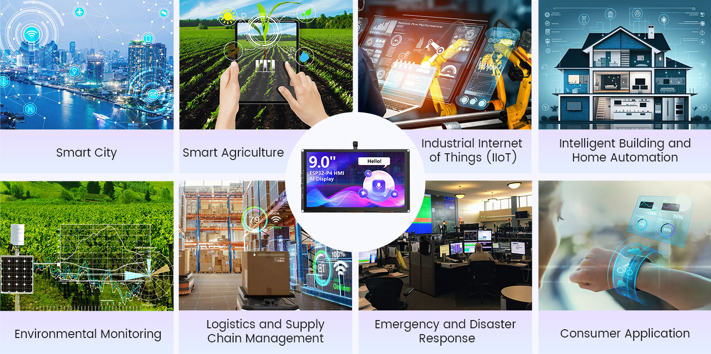
V porovnaní s predchádzajúcimi generáciami (Basic/Advanced ESP32-S3) dosahuje séria ESP32-P4 HMI významný pokrok v oblasti strojového učenia a výkonu spracovania údajov v reálnom čase vďaka vylepšenému procesoru a súboru inštrukcií AI. Či už ide o centrálne ovládanie inteligentnej domácnosti, priemyselný ovládací panel alebo komerčné zobrazovacie zariadenie, jeho komplexná podpora periférnych zariadení môže poskytnúť vynikajúce riešenia, ktoré vám pomôžu rýchlo vytvoriť výkonné a interaktívne inteligentné produkty.
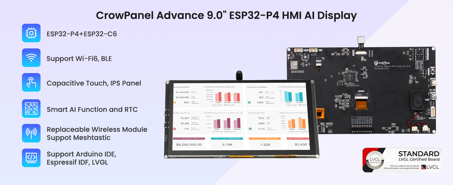
ESP32-P4+ ESP32-C6 dual chips

Integrated Intelligent AI Functions
Voice interaction is achieved through the microphone and speaker, allowing seamless conversations with the smart assistant and easy access to information.
The optional Camera provides AI Vision capabilities
Replaceable Wireless module design, easy to replace multiple protocols

Human-Machine Interface

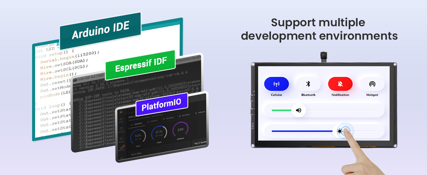
Support the LVGL development

Support multiple development environments
Application Scenario

Feature
✅ Powerful dual-core architecture, enhanced performance
✅ AI acceleration, fully upgraded performance
✅ High-definition IPS touchscreen for smooth and natural interaction
✅ Integrated intelligent vision, empowering AI applications
✅ Rich and comprehensive interfaces for flexible expansion
Application scenarios
Target Group:
Engineers and technicians, system integrators, facility managers, R&D personnel, agricultural workers, environmental scientists, medical professionals, retailers and restaurant owners, educational institutions, energy companies, etc.
|
Main Chip-ESP32-P4NRW32 |
|
|
CPU/SoC |
ESP32-P4 RISC-V 32-bit dual-core processor for HP systems, running at up to 400 MHz; RISC-V 32-bit single-core processor for LP systems, running at up to 40 MHz |
|
System Memory |
|
|
Memory |
|
|
Development Language |
MicroPython, Rust, Lua |
|
Development Environment |
ESP-IDF、Arduino IDE、LVGL |
|
Screen |
|
|
Size |
9.0 inch |
|
Resolution |
1024*600 |
|
Display Panel |
IPS Panel |
|
Touch Panel |
Capacitive Touch, Single/5-point Touch |
|
Viewing Angle |
178° |
|
Brightness |
400 cd/m²(Typ.) |
|
Color Depth |
16.7M (8-bit) |
|
Wireless Communication - Onboard Antenna |
|
|
WiFi |
Support 2.4GHz(Wi-Fi6), 802.11a/b/g/n |
|
Bluetooth |
Support Bluetooth 5.3 and BLE |
|
Other |
Zigbee、LoRa、nRF2401、Matter、Thread and Wi-Fi Halow (Optional) |
|
Interface/Function |
|
|
Interface |
USB2.0, UART, I2C, GPIO female headers, SD card holder, battery socket, speaker jack, camera header, module female headers, etc. |
|
Function |
Audio amplifier, battery charge management, USB to UART, dual microphones, etc. |
|
Button/LED Indicator |
|
|
Reset Button |
Yes, press to reset device |
|
Boot Button |
Yes, press and hold the power button to burn the program |
|
Power Button |
Switch On/Off |
|
PWR |
Device power on/off indication |
|
CHG |
Lithium battery charging status, Low battery state |
|
Other |
|
|
Installation method |
All around mounting holes(M3 3.2mm), embedded, shell assembly |
|
Operating temperature |
-20~70 °C |
|
Storage temperature |
-30~80 °C |
|
Power Input |
5V/2A, USB or UART terminal |
|
Dimensions |
222*130*16mm |
Three Wireless Module Details
|
Pin |
Pin Direction |
Note |
|
U1RXD |
Input |
Serial port 0 receiving pin |
|
U1TXD |
Output |
Serial port 0 receiving pin |
|
GPIO12 |
Input/Output |
GPIO |
|
GPIO13 |
Input/Output |
GPIO |
|
GPIO14 |
Input/Output |
GPIO |
|
3V3 |
|
Power supply |
|
GND |
|
Ground wire, connected to the power reference ground |
|
GPIO1 |
Input/Output |
GPIO |
|
GPIO0 |
Input/Output |
GPIO |
|
GPIO2 |
Input/Output |
GPIO |
|
GPIO22 |
Input/Output |
GPIO |
|
GPIO10 |
Input/Output |
GPIO |
|
GPIO11 |
Input/Output |
GPIO |
|
BOOT |
Press and then tap the RST key to enter the burning mode |
|
|
RST |
Press it to re-run the program and also to burn the program. |
|
Chip performance
|
Chip Model |
ESP32-H2FH4 |
|
|
FLASH |
4MB Quad SPI |
|
|
SRAM |
320KB |
|
|
ROM |
128KB |
|
|
LP memory |
4KB |
|
|
Ambient temperature |
-40℃~105℃ |
|
|
Voltage |
3.3V |
|
|
Bluetooth Low Energy Radio Specifications |
||
|
Working channel center frequency range |
2402~2480MHz |
|
|
RF transmission power range |
-24.0~20.0dBm |
|
Patch Antenna Performance
|
Gain and efficiency |
Bandwidth 2.4G~2.5GHz |
|
Peak Gain |
4.33dBi |
|
Average Gain across the band |
4.0dBi |
|
Gain Range across the band |
3.59dBi~4.33dBi |
|
Peak Efficiency |
62.5% |
|
Average Efficiency across the band |
57.5% |
|
Efficiency Range across the band |
51.3%~62.5% |
|
Pin |
Pin Direction |
Note |
|
CE |
Input |
Module control pin |
|
SCK |
Output |
SPI Data Pin |
|
MISO |
Input |
SPI Data Pin |
|
MOSI |
Output |
SPI Data Pin |
|
3V3 |
|
Power Supply |
|
GND |
|
Ground wire, connected to the power reference ground |
|
CSN |
Input |
Module chip select pin, used to start an SPI communication |
|
IRQ |
Input |
Module interrupt signal output, low level is effective |
Chip performance
Patch Antenna Performance
|
Gain and efficiency |
Bandwidth 2.4G~2.5GHz |
|
Peak Gain |
3.74dBi |
|
Average Gain across the band |
3.66dBi |
|
Gain Range across the band |
3.45dBi~3.74dBi |
|
Peak Efficiency |
58.9% |
|
Average Efficiency across the band |
55.9% |
|
Efficiency Range across the band |
53.0%~58.9% |
|
Pin |
Pin Direction |
Note |
|
DIO1 |
Input/Output |
Configurable general purpose IO ports |
|
SCK |
Input |
SPI Data Pin |
|
MISO |
Input |
SPI Data Pin |
|
MOSI |
Output |
SPI Data Pin |
|
3V3 |
|
Power supply |
|
GND |
|
Ground wire, connected to the power reference ground |
|
NRESET |
Output |
Chip reset trigger input pin, low level is effective |
|
DIO2 |
Input |
RF switch send/receive control pin, low level is receiving, high level is sending |
|
BUSY |
Output |
Used for status indication |
|
NSS |
Input |
Module chip select pin, used for SPI communication |
|
DIO3 |
Input/Output |
Configurable general purpose IO ports |
Antenna Performance
|
Gain(dBi) |
3.5dBi |
|
VSWR |
<=1.9 |
|
Input impedance(Ω) |
50 |
|
Polarization |
Vertical |
|
Lightning Protection |
DC Ground |
|
Mechanical Specification |
|
|
Wire Spec |
RF1.13 |
|
Wire length(cm) |
10cm |
|
Input connector type |
IPEX-1 |
|
Antenna weight(kg) |
0.01 |
|
Operating temperature |
-40℃~85℃ |
Display Pin Definition
|
Pin |
Description |
Connector Type |
|
SPK |
Output audio signal and connect to speakers. The mainboard has a power amplifier chip circuit. |
PH2.0-2P |
|
PWR |
Power LED |
|
|
RST |
Reset button. Press it to reset the system. |
|
|
BOOT |
|
|
|
UART0-OUT |
Build communication between Logic modules, including serial communication module and printing module. |
HY2.0-4P |
|
UART1-OUT |
Build communication between Logic modules, including serial communication module and printing module. |
HY2.0-4P |
|
UART1-IN |
|
HY2.0-4P |
|
I2C-OUT |
Establish communication between microcontroller and peripheral devices. |
HY2.0-4P |
|
BAT |
Connect lithium battery. (With battery charging circuit) |
PH2.0-2P |
For more pin functions, see Wiki.
Specific References
CrowPanel Advanced 9inch, ESP32-P4 HMI AI Display 1024x600 IPS Touch Screen , WiFi 6 Support (DHE04209D)
52.95 € tax excl.