


RLX COMPONENTS s.r.o. , Electronic Components Distributor.
RLX COMPONENTS s.r.o. , Electronic Components Distributor.

209.00 € tax excl.
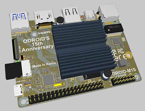
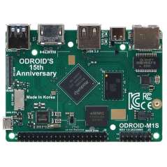
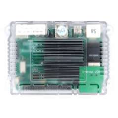
ODROID-M1S with 8GByte RAM + IO Header, SOC RK3566 , On-board eMMC & M.2 NVMe slot
ODROID-M1S with 8GByte RAM + IO Header, SOC RK3566 , On-board eMMC & M.2 NVMe slot
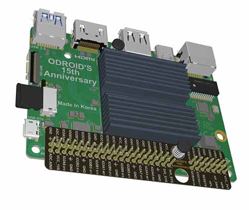
We made the board about 20% thinner, reduced power consumption by about 20%, added 14 header pins, and a built-in 64GB eMMC chip on the board. We have lowered the price including a case, heatsink, and power adapter. We believe this will help significantly reduce the cost of building your own affordable and sustainable embedded systems. To ensure longevity, which is important to customers using it for industrial purposes, we will supply this product until at least 2036.
WIKI : https://wiki.odroid.com/odroid-m1s/odroid-m1s
The SOC in the M1S is the RK3566, which is the younger sister of the RK3568 used in the original M1. This allows most of the software development to be reused. Because the bootloader and kernel settings are different, existing OS images for M1 cannot be used as-is, but porting is quickly possible through a simple process.
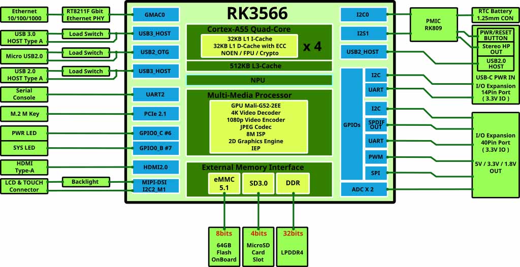
For detailed internal configuration, please refer to the block diagram below.
For the first time in the ODROID board series, an eMMC chip was soldered to the PCB by default instead of using a removable eMMC module. We think 64GB capacity is sufficient for building most embedded systems.
The speed of eMMC measured with the fio command is approximately 180MiB/s, which is about 3~5 times faster than typical microSD cards.
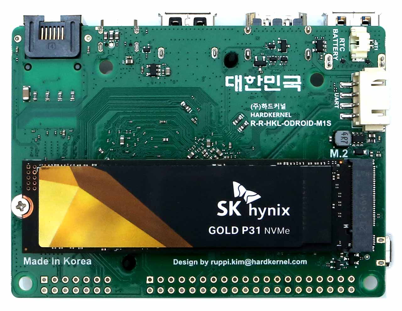
In case the 64GB storage space of the soldered eMMC memory is insufficient, consider using an industry standard 2280 form factor NVMe SSD. An on-board M.2 NVMe slot is provided to access large amounts of data storage.
Unlike the original M1 model’s PCIe 3.0 x 2 lanes configuration, M1S has PCIe 2.1 x 1 lane. The NVMe transfer speed of the M1S has been reduced by about 1/4. However, we still believe that ~400 MiB/s of storage access speed is sufficient for building various high-end embedded systems.
Note that M.2 SATA storage devices can not be used. The M.2 slot supports only a PCIe interface (M-Key).
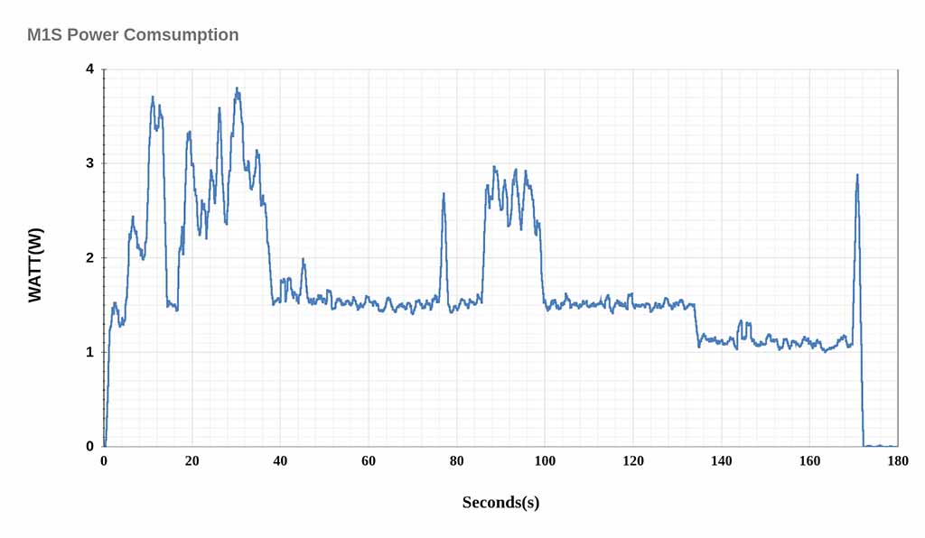
To create the graph below, we turned on the M1S and recorded the power consumption until the Ubuntu Desktop OS boots and enters Idle mode. We used the SmartPower3 device to examine power characteristics.
-With Ethernet and HDMI monitor connected, the peak power consumption is close to 3.7 Watts during booting, but drops to 1.5 Watts in desktop GUI idle state.
-If you remove the HDMI monitor for a headless system, power consumption in idle mode drops to near 1.0 Watt. Additionally, please note that when the Ethernet cable is unplugged, the power drops to 0.7 Watt.
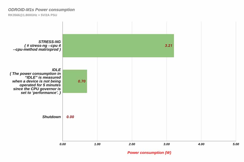
When performing a CPU stress test without either HDMI output or Ethernet connection, the power consumption is about 3.2 Watts. This shows an energy savings of about 25% compared to the 4.3 Watts of the original ODROID-M1 under the same test conditions. Note that the computing power of ODROID-M1S has been measured to be 5-10% lower than that of M1.
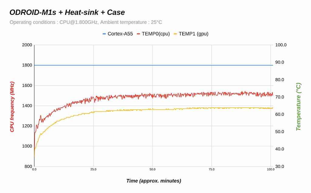
Thermal throttling does not occur even when performing a CPU stress test while mounted in a case. Because system power consumption is low, less heat is generated. Cooling is sufficient with just the stock heatsink.
As shown in the graph below, when a stress test was performed on ODROID-M1S with a stock heatsink under room temperature conditions of 25°C, the CPU temperature did not exceed 65°C and maintained the maximum clock frequency.
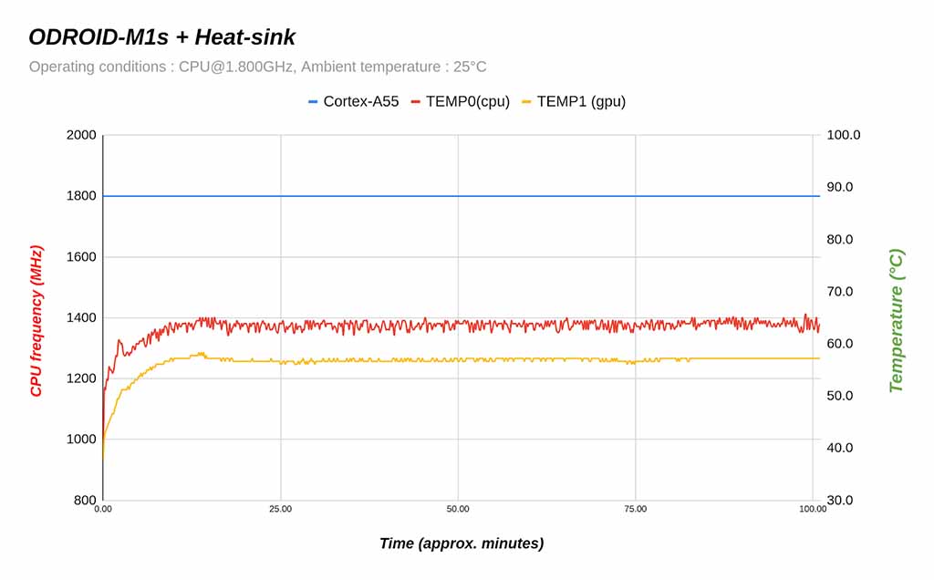
Even when assembled in the case, the CPU temperature did not exceed 75°C and thermal throttling did not occur.
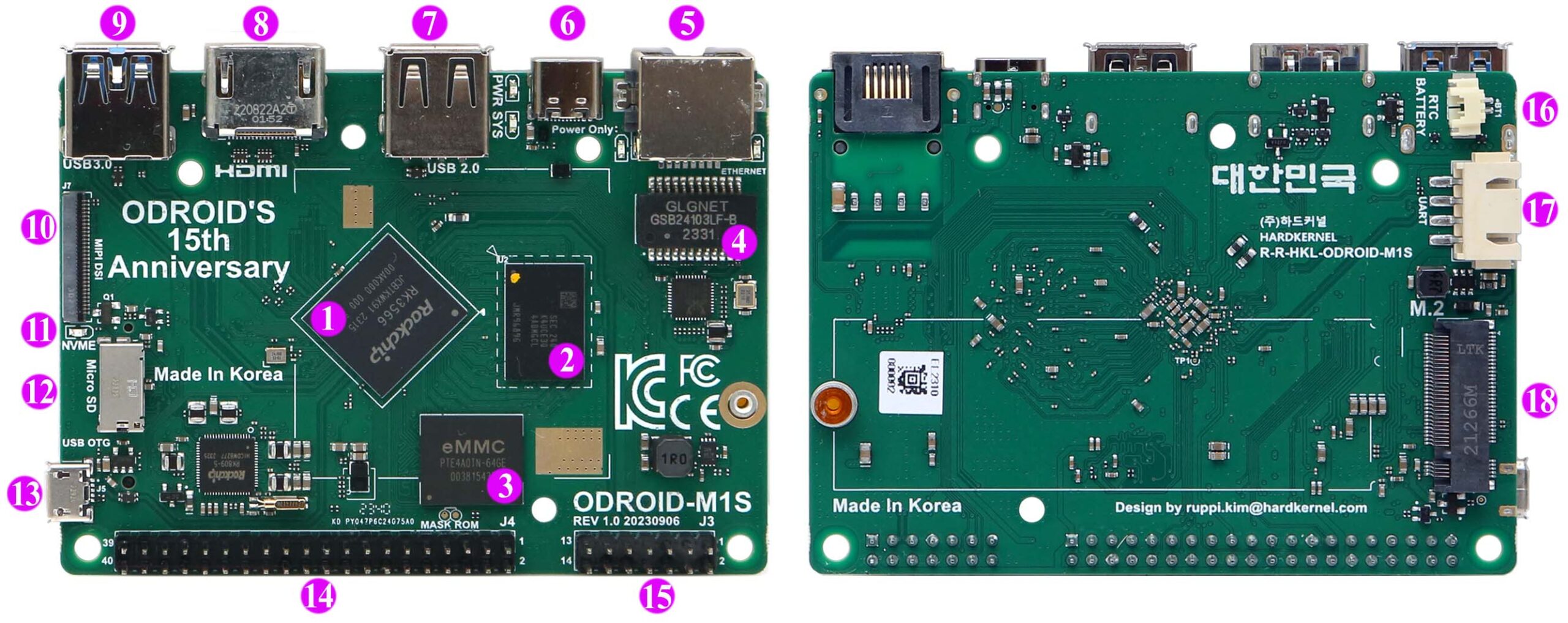
| 1 | Rockchip RK3566 CPU | 10 | 1 x MIPI DSI 4Lane |
| 2 | LPDDR4 RAM | 11 | 1 x M.2 LED Indicator |
| 3 | 1 x 64GB eMMC embedded | 12 | 1 x Micro SD Slot |
| 4 | 1 x Ethernet Transformer | 13 | 1 x Micro USB2.0 OTG |
| 5 | 1 x RJ45 Ethernet Port (10/100/1000) | 14 | 40 x GPIO Pins Optional |
| 6 | 1 x USB Type C Power Connector | 15 | 14 x GPIO Pins Optional |
| 7 | 1 x USB 2.0 | 16 | 1 x RTC Backup Battery Connector |
| 8 | 1 x HDMI 2.0 | 17 | 1 x UART for System Console |
| 9 | 1 x USB 3.0 | 18 | 1 x M.2. M-KEY PCIe2.1 1Lane |
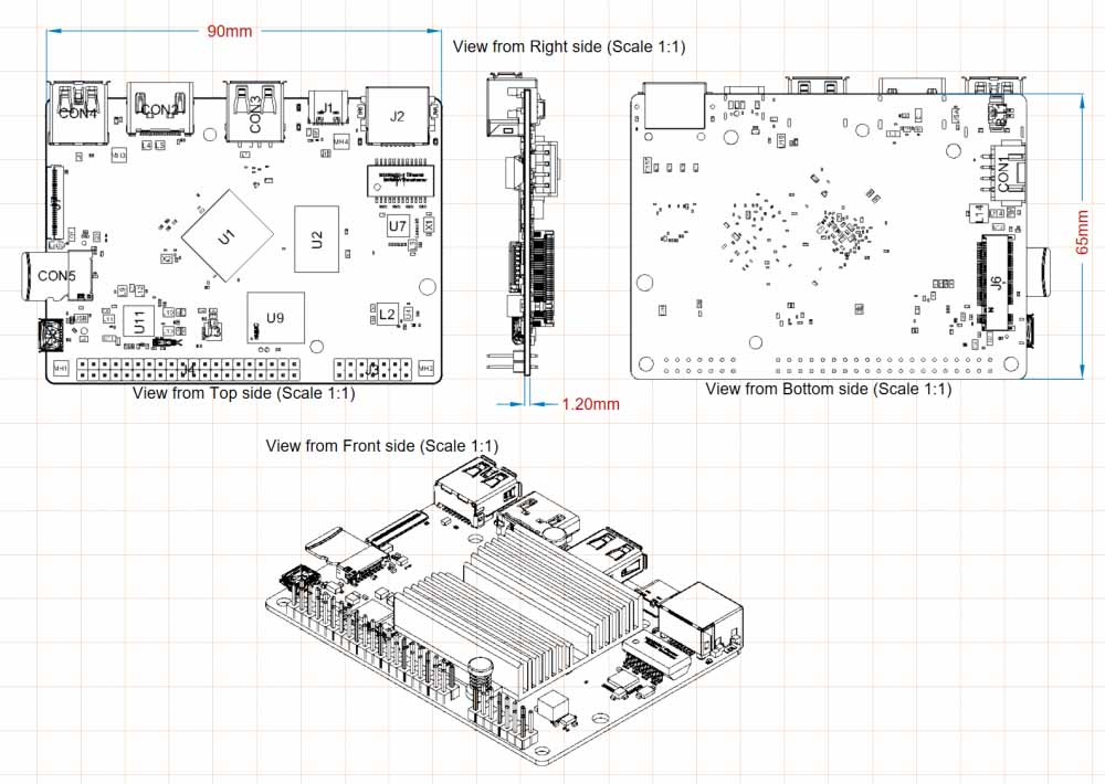
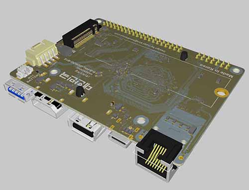
| FORM FACTOR | Board Dimensions: 90mm x 65mm x 16mm Weight: 52g including heatsink |
|---|---|
| PROCESSOR | Rockchip RK3566 Processor L1 instruction cache: 32 KB, 4-way set associative (128 sets), 64 byte lines, shared by 1 processor L1 data cache: 32 KB, 4-way set associative (128 sets), 64 byte lines, shared by 1 processor L3 data cache: 512KB , 16-way set associative (512 sets), 64 byte lines, shared by 4 processorsQuad-Core Cortex-A55 (1.8GHz) ARMv8-A architecture with Neon and Crypto extensions Mali-G52 MP2 GPU with 4 x Execution Engines (800Mhz) |
| NPU | 0.8 TOPS@INT8, Integrated AI accelerator RKNN NPU Supports one-click switching of Caffe/TensorFlow/TFLite/ONNX/PyTorch/Keras/Darknet |
| MEMORY | LPDDR4 4 or 8GiB with 32-bit bus width, Data rate: 2112 MT/s, up to 1,055MHz |
| STORAGE | 1 x 64GB eMMC embedded (soldered to the PCB) 1 x Micro SD slot (UHS-I SDR104, Boot priority is always higher than eMMC) 1 x NVME M.2 SSD (PCIe 2.1 x 1 lane) |
| NETWORKING | 1 x GbE LAN ports (RJ45, supports 10/100/1000 Mbps) – Realtek RTL8211F Ethernet transceiver – LED indicators * Green LED: Flashing by data traffics at 100Mbps connection * Amber LED: Flashing by data traffics at 1000Mbps connection |
| VIDEO | 1 x HDMI 2.0 (up to 4K@60Hz with HDR, EDID) 1 x MIPI DSI Interface (30pin connector which is different from 31pin of the original ODROID-M1) |
| EXTERNAL I/O | 1 x USB 2.0 host port 1 x USB 3.0 host port 1 x USB 2.0 micro OTG port 1 x Debug serial console (UART) 1 x 40 pin GPIO and 1 x 14 pin GPIO |
| OTHER FEATURES | RTC backup battery connector (to keep time and date for several months without main power input) System LED Indicators: – Red (POWER) – Solid light when DC power is connected – Blue (ALIVE) – Flashing like heartbeat while Kernel is running. Solid On in the u-boot stage. |
| POWER | 1 x USB Type C for Power only DC input : 4.9V ~ 5.3V – USB Type C 5V/3A power adapter is recommended – IDLE : ≃ 1.1W – CPU Stress : ≃ 3.52W (Performance governor) – Power Off : ≃ 0W |
-The CPU has four ARM Cortex-A55 processors with low power consumption & high efficiency operation at 1.8Ghz. A larger 8GB of LPDDR4 DRAM memory is available in addition to a 4GB model for reduced cost.
There are 40-pin and 14-pin header pin connectors for general purpose input and output functions. Digital IOs, UARTs, I2Cs, PWMs, ADCs, SPI, USB 2.0 host, Analog audio output, Power-on and Reset signals are available.
What we heard from many B2B and B2C customers is that they often didn’t use the actual GPIO functionality. Therefore, to lower production costs and product price, we decided to make GPIO header pin installation an option. If you choose the option to install 40-pin and 14-pin GPIO headers, $3 will be added to the price. An IO-labels board for easier DIY tinkering will also be provided.

-The four-lane MIPI-DSI port can be directly connected to an LCD panel.
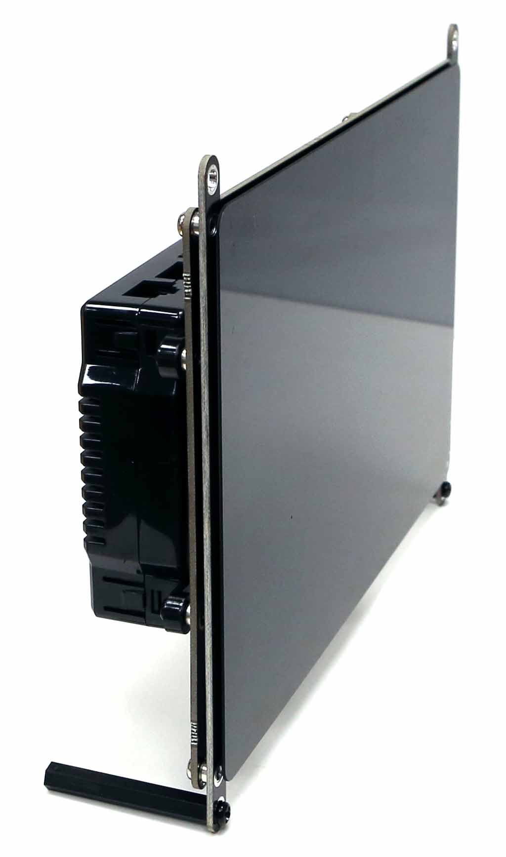
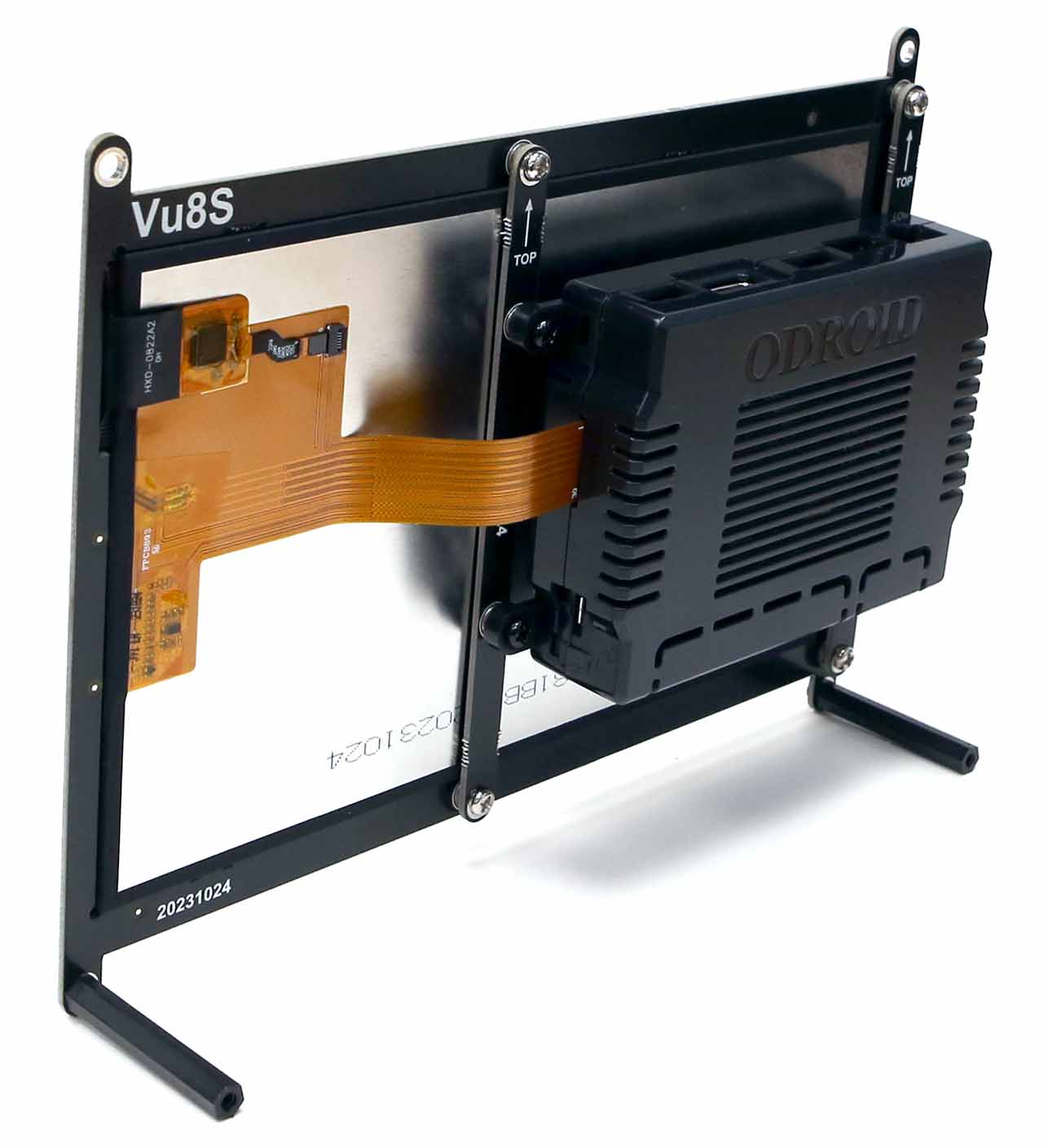
-The ODROID-Vu8S kit with an 8 inch, 800×1280 wide viewing angle LCD and capacitive multi-touch screen is an available option. Note that LCD connector is different from the one on the ODROID-M1.
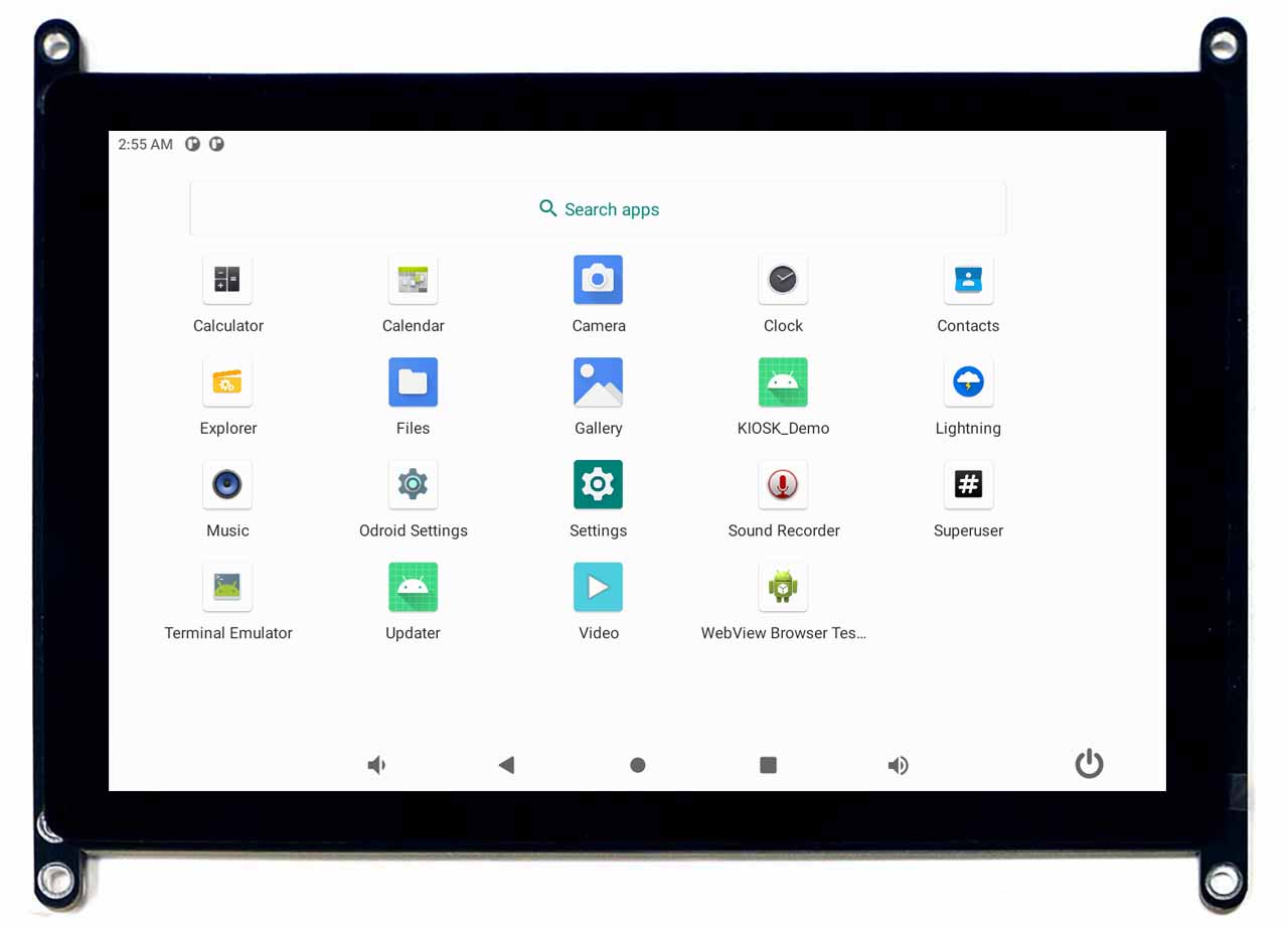
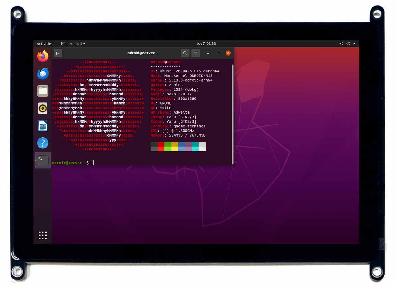
-If you assemble the ODROID-M1S single board computer on the rear side of the Vu8S kit, you can easily implement a Human-Machine-Interface (HMI) device with Android as well as Linux.
Since Machine Learning has been a trend in this industry, there is a neural network processing unit (NPU) which can deliver up to 0.8 TOPS on the M1S single board computer.
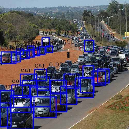
We could run various TensorFlow Lite and ONNX models on Ubuntu Linux OS. Here is an example of object detection.
– Input image and Output image ( The input image source : https://commons.wikimedia.org/wiki/File:Traffic_in_Brasilia_before_Brazil_%26_Chile_match_at_World_Cup_2010-06-28_1.jpg )
As shown in the test results below, the object detection speed of the NPU is nearly 20 times faster than that of the CPU. For reference,
the NPU performance of M1S is about 10% lower than that of M1. We believe this is due to the difference in DRAM clocks.
| Conf=0.25 | CPU (ms) | NPU (ms) | NPU: Cam (fps) |
| M1S | 1288.3 | 70 | 11.8 |
| M1 | 1225.7 | 64.3 | 13 |
CPU governor = performance
AI model = yolov5s.onnx(cpu) / yolov5s.rknn(npu)
Confidence threshold = 0.25
USB Camera = Logitech BRIO

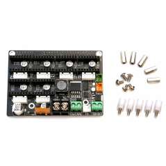
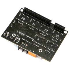
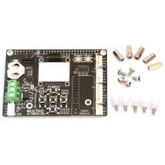
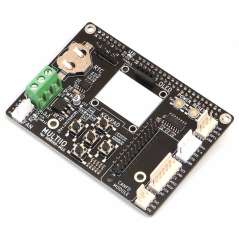
M1S + 6 channel stepper motor board and actual 3D printer operation video (via YouTub
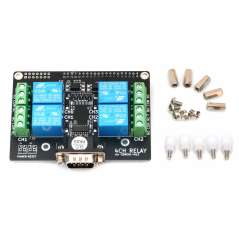
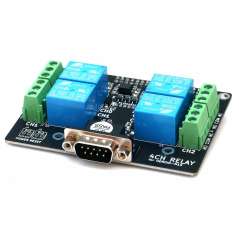
M1S + 4Channel Relay board controlling a home sy
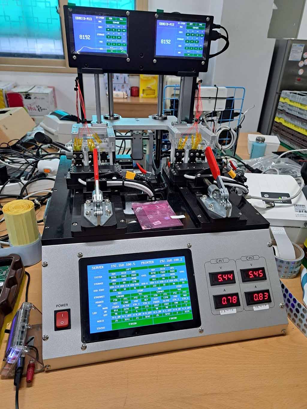
-The ODROID-M1S board is 100% inspected in our internal facility. We are proud to say that the automated equipment that inspects ODROID-M1S products is also equipped with three ODROID-M1S boards, which act as the brain. Thanks to the ODROID-M1S powered smart equipment, we can produce more than 500 units per day. This is a good example showing that ODROID-M1S can be used practically in real industry.
We provide comprehensive documentation for nearly 100 items through our WiKi pages and Github.
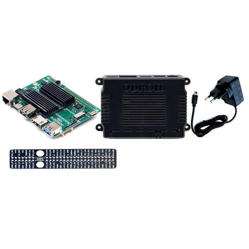
Balenie Obsahuje / Package Content
Specific References
209.00 € tax excl.
6.90 € tax excl.
29.90 € tax excl.
4.80 € tax excl.
19.40 € tax excl.
17.50 € tax excl.
16.50 € tax excl.
17.50 € tax excl.
ODROID-M1S with 8GByte RAM + IO Header, SOC RK3566 , On-board eMMC & M.2 NVMe slot
209.00 € tax excl.