
RLX COMPONENTS s.r.o. , Electronic Components Distributor.
RLX COMPONENTS s.r.o. , Electronic Components Distributor.
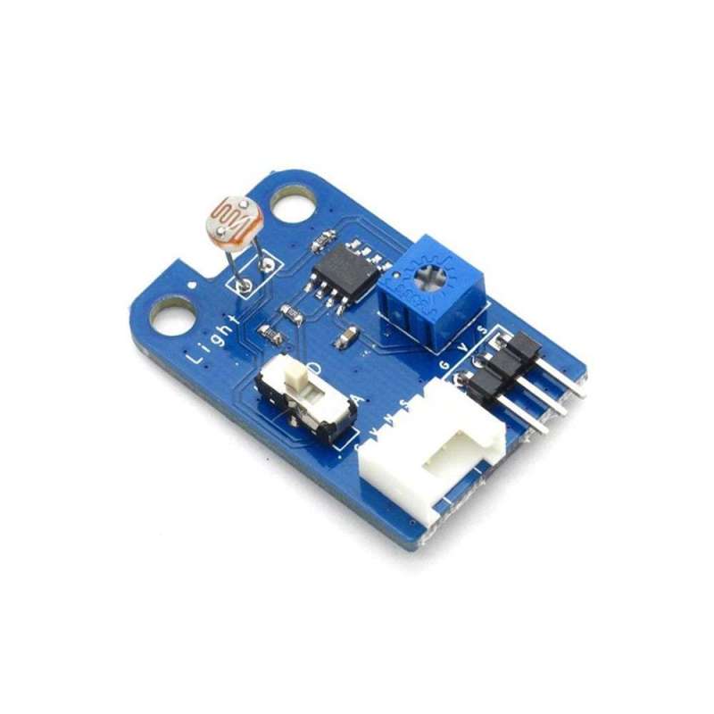
LIGHT SENSOR BRICK (Itead IM120710017) CdS PHOTOCONDUCTIVE CELLS GL5528
With switch to shift between analog and digital output. Able to read the specific light intensity information (analog) or the over-bright or over-dark information according to the threshold (digital). The adjustable potentiometer is used to set the light intensity threshold. With hysteresis comparator circuit for more stable digital output voltage.

4. Detecting direction can be rotated for better adaption

| PCB size | 36.0mm X 24.0mm X 1.6mm |
| Working voltage | 3.3 or 5V DC |
| Operating voltage | 3.3 or 5V DC |
| Compatible interfaces | 2.54 3-pin interface and 4-pin Grove interface(1) |
Note 1: D for digital output port, A for analog output port, S for analog/digital output port ( defined according to the switch), V and G for voltage at the common collector and ground respectively
Note 2: When setting as analog output, output range is 0-3.3V or 0-5V according to the working voltage (V,G); when setting as digital output, output is 0/3.3V or 0/5V according to the working voltage (V,G).
| Parameter | Min. | Typical | Max. | Unit |
| Working voltage | 2.1 | 5 | 5.5 | VDC |
| Analog output voltage(VCC=5V) | 0 | Vout | 5 | V |
| Digital output voltage(VCC=5V) | 0 | - | 5 | V |
| Working current(VCC=5V) | - | 5 | - | mA |
| Photoresistor(light intensity is 10lux) | 5 | - | 10 | kohm |
| Threshold hysteresis ΔUth | - | VCC*0.09 | - | V |


1. Regulating of threshold voltage:
The threshold voltage is a voltage for comparison. When the light intensity value read by the sensor is above the threshold value, a low level (0V) will be digitally output; when the light intensity value read by the sensor is below the threshold value, a high level (3.3V or 5V) will be digitally output. In this way, the digital pin can be used directly to read the current light intensity value in the environment to see if it is above the threshold or not. The threshold voltage can be regulated by simply twisting the potentiometer which is shown in Figure 1, and it increases by rotating to left side and decreases by rotating to right side.

2. Switch to shift between analog and digital output
For S pin in 4-pin Grove interface and 2.54mm 3-pin interface, it outputs analog signals when switch is pushed to A terminal and digital signals when pushed to D terminal. When there is analog signal output, it can read the specific light intensity value; when there is digital signal output, it can only indicate whether the light intensity value is above threshold value or not.