
RLX COMPONENTS s.r.o. , Electronic Components Distributor.
RLX COMPONENTS s.r.o. , Electronic Components Distributor.
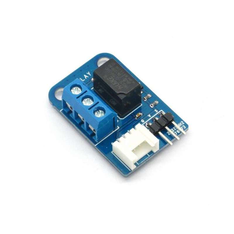
ELECTRONIC BRICK - 5V RELAY (IM120710007) RELE Arduino,AVR,PIC,...
Plug and play, easy to use. Compatible with the mainstream 2.54 interfaces and 4-Pin Grove interfaces in the market.

2. With use of M4 standard fixed holes, compatible with M4-standard kits such as Lego and Makeblock.

3. With protection circuit to prevent from burning the relay coil when disconnected; with isolation circuit to prevent damages to I / O port by relay switch current .

4. With LED status lamp to indicate whether it is currently connected or not.

5. Terminals with screws for easy wiring and removing

| PCB size | 36.0mm X 24.0mm X 1.6mm |
| Working voltage | 5V DC |
| Operating voltage | 5V DC |
| Compatible interfaces | 2.54 3-pin interface and 4-pin Grove interface(1) |
Note 1: S for digital output port, V and G for voltage at the common collector and ground respectively
| Parameter | Min. | Typical | Max. | Unit |
| Working voltage | 4.5 | 5 | 5.5 | VDC |
| Digital input voltage(VCC=5V) | 0 | - | 5 | V |
| Working current(VCC=5V) | - | 34 | - | mA |
| Maximum Switch current | - | 2 | - | A |
| Maximum Switch AC | - | 120 | - | VAC |
| Maximum Switch DC | - | 24 | - | VDC |
Status lamp
For NO and COM ports, when relay is connected, LED lamp will be ON; when relay is disconnected, LED lamp will be off.
Connect S port of electronic brick of relay to D2 port of Arduino board, then connect COM and NO ports of relay in series to loop of LED, and we will use the following program to make LED lamp flash at intervals of 1s.
|
1
2
3
4
5
6
7
8
9
10
11
12
|
int relay = 2;void setup() { // initialize the digital pin as an output. pinMode(relay, OUTPUT); }void loop() { digitalWrite(relay, HIGH); // turn the relay on(HIGH is the voltage level) delay(1000); // wait for a second digitalWrite(relay, LOW); // turn the relay on by making the voltage LOW delay(1000); // wait for a second} |