

")
")
")
")
")
")
RLX COMPONENTS s.r.o. , Electronic Components Distributor.
RLX COMPONENTS s.r.o. , Electronic Components Distributor.

32.90 € bez DPH
USB Logic Analyzer - 25MHz/8-Channel (SF-TOL-15033)
USB Logic Analyzer - 25MHz/8-Channel (SF-TOL-15033)
Description
Is your I2C bus not ACK'ing the way you expect? Do you need to discover a UART's mysterious baud rate? Or do you want to reverse engineer an SPI protocol? These all sound like jobs for a logic analyzer! With the growing ubiquity of UART, I2C, and SPI sensors, logic analyzers are becoming a tool everyone needs in their toolbox or on their workbench. This 8-channel USB Logic Analyzer with support for sampling rates of up to 24MHz provides a good while economic option making it a great tool for quickly diagnosing most communication issues we encounter. These analyzers will work with both 3.3V and 5V systems (up to 5.25V max and 2.0V minimum on a high logic-level) and is powered via an included mini-B USB cable. This logic analyzer works with PulseView -- an open-source, cross-platform signal analysis software suite. The analyzer ships with Female-To-Female jumper wires. If you're using an Uno or board with female headers we recommend picking up a handful of Male-To-Male jumpers to connect the analyzer to the female headers.
Features
Includes
Documents
Using the 8Ch/24MHz Logic Analyzer with sigrok
Download the latest PulseView release from sigrok's Downloads page. Here are direct links for the latest Windows, Mac, and Linux downloads:
Windows users can run the installer executable (pulseview-NIGHTLY-32bit-static-release-installer.exe) to install the software on your machine. The Mac installer is a binary disk image (DMG), which can be dragged into your Applications folder, for example.
With PulseView open, plug in your USB Logic Analyzer. You should see faint red and green LEDs illuminate under the sticker.
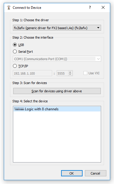
If PulseView does not automatically detect your logic analyzer, you'll need to set it manually:
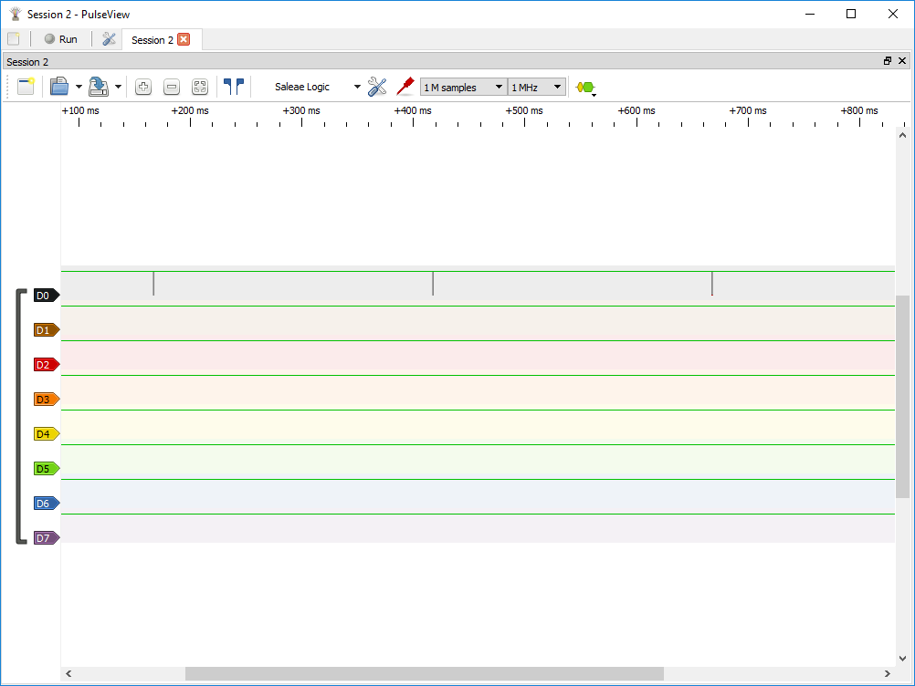
You'll be greeted with a blank slate of eight colorful bands of logic channels, numbered D0 to D7 (these match the CH0-CH7 labels on the LA).
Click the Run button in the top-left of the window to beginning scanning.
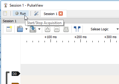
With the sampling parameters set as default -- 1M samples, 20kHz -- it'll take almost a minute to gather all million samples. You can hit "Stop" to end the scan early.
Unless you've already connected a few channels and grounds, this first scan will probably not be that interesting.
Note: This example assumes you are using the latest version of the Arduino IDE on your desktop. If this is your first time using Arduino, please review our tutorial on installing the Arduino IDE.
Here's a fun, tormenting Arduino sketch you can load to help familiarize yourself with PulseView's capabilities:
void setup() {
// put your setup code here, to run once:
randomSeed(analogRead(A0));
Serial.begin(random(1, 115200)); // Set the baud rate to a random value between 1 and 115200 bps
}
void loop() {
Serial.println(millis()); // Print the time
delay(250);
}
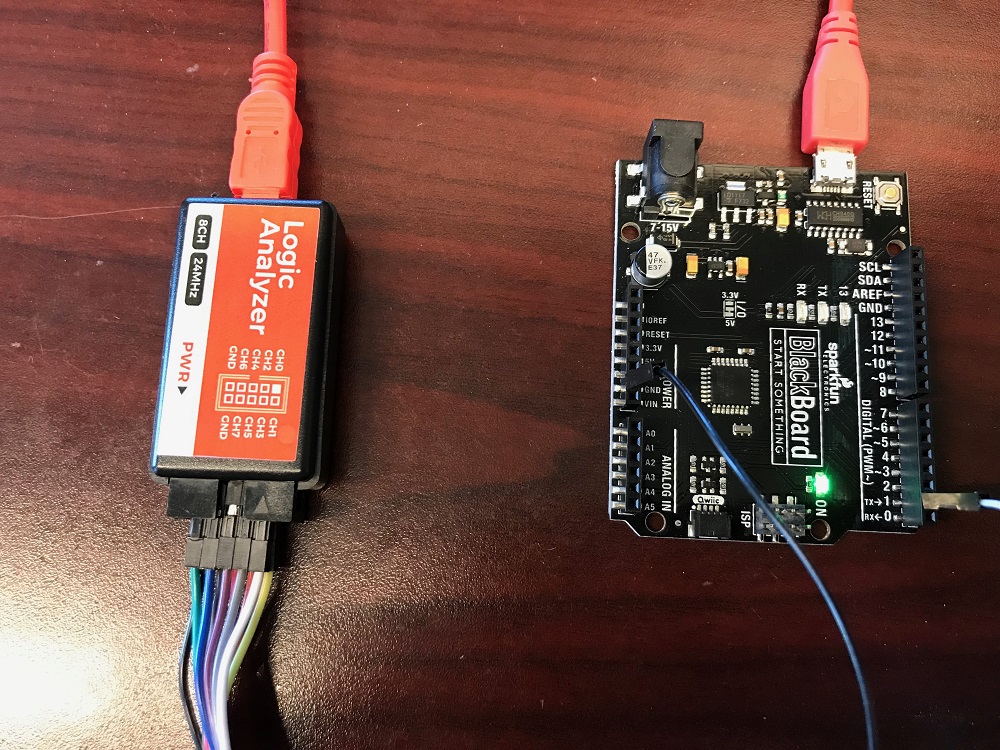
Load that onto an Arduino, then connect the logic analyzers "CH0" to your Arduino's TX pin (pin 1). Also connect on of the GND wires to GND.
Before scanning, bump up the sample rate to 1MHz and change the sample quantity to 1 M samples. Depending on what you're trying to analyze, these dropdowns may get a lot of use. With those values set, hit Run.
You should be greeted with a seconds worth of samples, and a few blips on the D0 channel every 250ms.
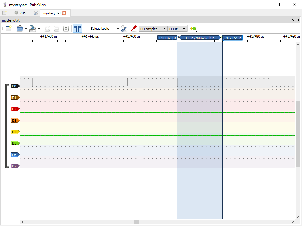
You can use your mouse's scroll wheel to zoom in and out, or use the "+" and "-" buttons on the toolbar. Zoom into one of the blips. Now it's your job to guess the baud rate!
The Show cursors (pair of blue flags icon) tool can be useful for measuring time. Click that, then try to place the cursors around one bit of the transmission. The measured frequency should be our mystery baud rate!
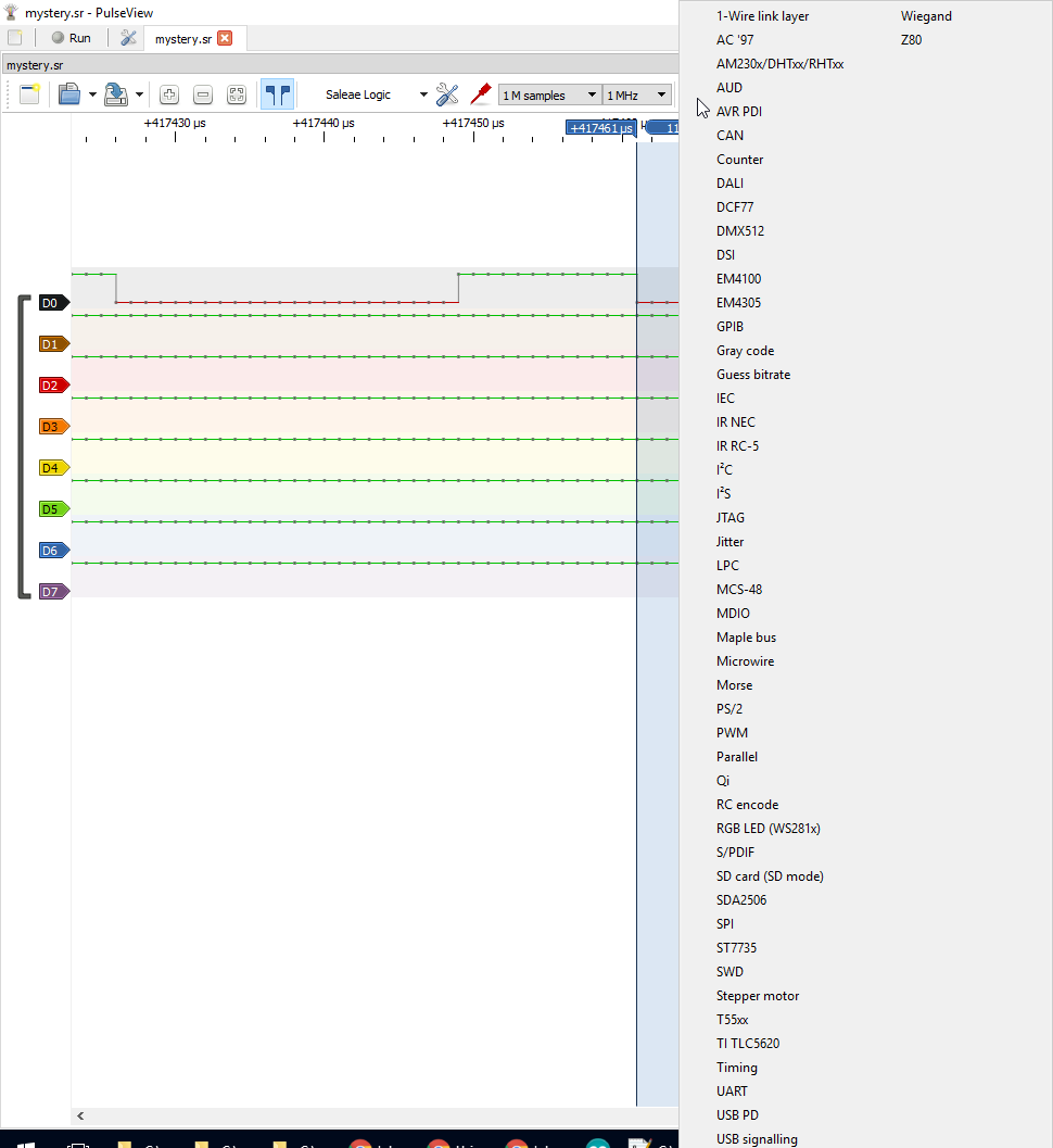
To decode the string, use the Add low-level, non-stacked protocol decoder tool (looks like yellow and green decoded signals). Then select UART -- note that a huge list of protocols pops up here, including I2C, I2S, SDIO, and SPI.
Click the green "UART" icon that appears towards the bottom-left and change the baud rate to your measured frequency. You can also change the data format to ascii to make the data easier to parse.
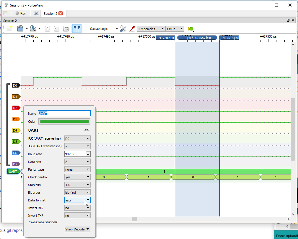
Now if you zoom out you should see your serial prints decoded!
For more information, check out the resources below:
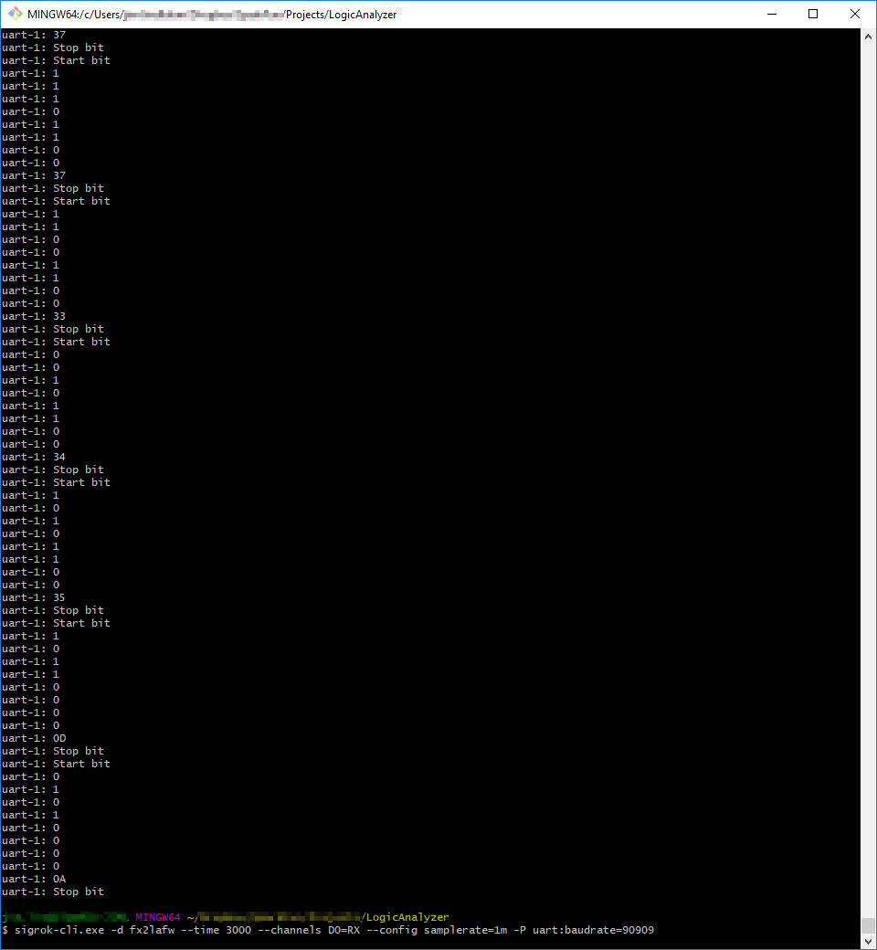
If you're connecting the logic analyzer to a headless machine, or want to automate a LA-based test, check out sigrok-cli -- a command line interface for sigrok. With sigrok-cli installed, for example, you can use a command like:
sigrok-cli.exe -d fx2lafw --time 3000 --channels D0=RX --config samplerate=1m -P uart:baudrate=115200
To decode a UART connected to channel 0.
The CLI has a lot of potential for automation, and the main page is super-helpful!
As you venture into this world of logic analyzing, be sure to try out all of PuseView's protocol decoders and features. It's a great software tool and has a powerful open-source community behind it.
Špecifické referencie
USB Logic Analyzer - 25MHz/8-Channel (SF-TOL-15033)
32.90 € bez DPH