

 digital and analogue expansion board")
 digital and analogue expansion board")
 digital and analogue expansion board")
 digital and analogue expansion board")
RLX COMPONENTS s.r.o. , Electronic Components Distributor.
RLX COMPONENTS s.r.o. , Electronic Components Distributor.
")
Expander Pi (AB Electronics UK) digital and analogue expansion board
Expander Pi (AB Electronics UK) digital and analogue expansion board
Expander Pi is a versitile digital and analogue expansion board. It allows you to connect your Raspberry Pi to switches, lights, sensors, and many other devices giving you a way to communicate with the outside world.
The Expander Pi plugs onto the GPIO port on your Raspberry Pi and can be securely fitted to the Raspberry Pi using the optional mounting kit. It is powered through the host Raspberry Pi using the GPIO port or via the on-board power connetor. Extended pins on the GPIO connector allowing you to stack the Expander Pi along with other expansion boards.
Features:
Using the Expander Pi you can connect 8 analogue inputs, 2 analogue outputs and 16 digital input or outputs to your Raspberry Pi. The Expander Pi also features an on-board Real Time Clock (RTC) to ensure that your Raspberry Pi always has the correct date and time.
Mounting holes are provided so you can securely bolt the Expander Pi to your Raspberry Pi with our mounting kit (sold separately).
The 16 input and output channels, using MCP23017 16-bit I/O expander from Microchip Technology Inc, can be independently configured as either inputs or outputs with a maximum input of 5 volts on each channel.
The 2 channel digital to analogue converter is a 12 bit resolution using Microchip MCP4822 dual channel 12-bit DAC with an internal voltage reference.
The 8 analogue to digital converter is a 12 bit resolution using a Microchip MCP3208 8-Channel 12-Bit A/D Converters with SPI Serial Interface with a maximum sample rate of 100 ksps and includes a 4.096 volt precision voltage reference. Please note the maximum sample rate is dependant on the programming language used and the CPU speed and usage. A seperate Vref pin is included allowing you to use an external voltage reference. If you do choose to use an external voltage reference you will need to disconnect the onboard voltage reference IC by removing the solder bridge from jumper J1. Failing to remove the J1 solder bridge when using an external reference could cause damage to the onboard voltage reference or your external reference circuitry.
The Real Time Clock uses the DS1307 RTC real time clock and a CR2032 battery to maintain the date and time when the main system power is not available.
Warning: Do not connect the Expander Pi to your Raspberry Pi when the power is connected without a CR2032 battery installed. This can cause damage to the DS1307 RTC chip.
The Expander Pi uses a CR2032 button battery (battery not included).
Due to the use of the SPI bus and fixed addresses on the I2C bus the Expander Pi can not be stacked along side the ADCDAC Pi Zero or RTC Pi Plus/Zero. Only one Expander Pi can be used on a Raspberry Pi.
The I2C address for the MCP23017 digital I/O chip is set to 0x20, if you use the Expander Pi with an IO Pi Plus/Zero you will need to ensure that the addresses for the IO Pi chips are not set to 0x20.
If you want to power the Raspberry Pi from the USB connector and use a seperate supply for powering the Expander Pi we recommend that you remove the solder bridge "JUMPER" next to GPIO pin 1 on the Expander Pi, disconnecting it from the Raspberry Pi 5V pins.
| Model | Status |
|---|---|
| Raspberry Pi Model A | No |
| Raspberry Pi Model B | No |
| Raspberry Pi 1 Model A+ | Yes |
| Raspberry Pi 1 Model B+ | Yes |
| Raspberry Pi 2 Model B | Yes |
| Raspberry Pi 3 Model B | Yes |
| Raspberry Pi Zero | Yes |
| Raspberry Pi Zero W | Yes |
The Expander Pi uses the SPI port and I2C addresses 0x20 and 0x68, please ensure that any additional expansion boards do not have an address conflict with these I2C addresses.
Please follow our tutorials for enabling I2C and SPI before using the Expander Pi on your Raspberry Pi.
The Expander Pi can be stacked with the following boards.
The Expander Pi is not compatible with the following boards:
Digital IO Input Ratings & Specifications
ADC Input Ratings & Specifications
DAC Output Ratings & Specifications
The Expander Pi is supplied with the 40 pin GPIO connector and the CR2032 battery connector unsoldered.
Before using the Expander Pi you will need to solder both connectors onto the PCB. We suggest soldering the 40 pin GPIO connector first and then the battery connector. Soldering the battery connector first will make it difficult to access some of the pins on the GPIO connector.
Watch the assembly video, best viewed in 1080p high quality mode:
Download and print our PCB Header Assembly Jig to hold your circuit board when soldering the header pins.
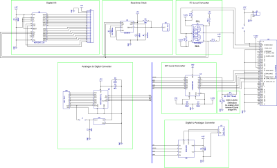
Click to download schematic PDF.

Click image to enlarge
We have Python, C, C++, Node.js and Windows 10 IOT libraries available for this expansion board. You can download all of the libraries from github at:
https://github.com/abelectronicsuk/ or click on the logos below for your selected programming language,
IO - Microchip MCP23017
ADC - Microchip MCP3208
DAC - Microchip MCP4822
RTC - Maxim DS1307
We have a range of tutorials for the Expander Pi in our Knowledge Base
Špecifické referencie
Expander Pi (AB Electronics UK) digital and analogue expansion board