

RLX COMPONENTS s.r.o. , Electronic Components Distributor.
RLX COMPONENTS s.r.o. , Electronic Components Distributor.
ADC Pi Plus (AB Electronics UK) 8-channel 17-bit analogue to digital converter for Raspberry Pi
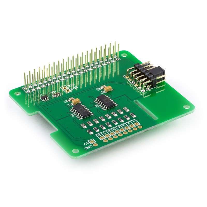
The ADC Pi Plus is an 8 channel 17 bit analogue to digital converter designed to work with the Raspberry Pi. The ADC Pi Plus is based on two Microchip MCP3424 A/D converters each containing 4 analogue inputs. The MCP3424 is a delta-sigma A/D converter with low noise differential inputs.
Note:
Disconnect the ADC Pi Plus from the Raspberry Pi before changing the address pins. You may need to short the 5V and ground with a resistor to discharge the capacitors in order for the new addresses to be recognised.
| Adr 0 | Adr 1 | I2C Address |
|---|---|---|
| Low or Float | Low or Float | 0x68 |
| Low | Float | 0x69 |
| Low | High | 0x6A |
| Float | Low | 0x6B |
| High | Low | 0x6C |
| High | Float | 0x6D |
| High | High | 0x6E |
| Float | High | 0x6F |
Do not under any circumstanced connect the two centre pins together. This will create a direct short between the 5V and ground pins and will damage or destroy your Raspberry Pi and ADC Pi Plus board.
Configuration 1:
Analogue Channels 1-4 = I2C Address: 0x68
Analogue Channels 5-8 = I2C Address: 0x69
Configuration 2:
Analogue Channels 1-4 = I2C Address: 0x6A
Analogue Channels 5-8 = I2C Address: 0x6B
Configuration 3:
Analogue Channels 1-4 = I2C Address: 0x6C
Analogue Channels 5-8 = I2C Address: 0x6D
Configuration 4:
Analogue Channels 1-4 = I2C Address: 0x6E
Analogue Channels 5-8 = I2C Address: 0x6F
| Spec | Rating |
|---|---|
| Vdd (5V pin on I2C bus) | 5.0V |
| All AD inputs and outputs | VSS–0.4V to VDD+0.4 V |
| Current at Input Pins | ±2 mA |
| I2C SDA/SCL voltage | 5.0 V |
| I2C port current | 100 mA |
Click to download schematic PDF.
The ADC Pi Plus is supplied with the 40 pin GPIO connector and the 12 pin address connector unsoldered.
Before using the ADC Pi Plus you will need to solder both connectors onto the PCB. We suggest soldering the 40 pin GPIO connector first and then the address select connector. Soldering the address select connector first will make it difficult to access the three corner pins on the GPIO connector.
Watch the assembly video, best viewed in 1080p high quality mode:
Download and print our PCB Header Assembly Jig to hold your circuit board when soldering the header pins.
Click image to enlarge
We have Python, Arduino, C, C++, Node.js and Windows 10 IOT libraries available for this expansion board. You can download all of the libraries from github at:
https://github.com/abelectronicsuk/ or click on the logos below for your selected programming language,
We have a range of tutorials for the ADC Pi and ADC Pi Plus in our Knowledge Base