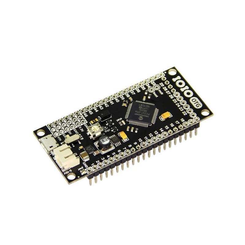
IOIO OTG for Android (Seeed KIT02600M) Ytai Ben-Tsvi
The IOIO-OTG is a board which allows you to quickly and easily interface electronic circuits to an Android device or a PC:
- Connect the IOIO-OTG to the Android / PC using USB or Bluetooth.
- Power the IOIO-OTG (not required if operating in USB device mode, see below).
- Connect your circuits to any of the 46 I/O pins available on the IOIO-OTG. You can power your circuits off of the IOIO-OTG too.
- Write a Java program to control the I/O pins, using a high-level API using the provided libraries.
The IOIO-OTG can be powered in one of two ways:
- By supplying 5V-15V to its JST connector. Do not exceed 10V if using long wires between the power supply and the IOIO-OTG or you might damage the board. The IOIO-OTG has an on-board 5V switching regulator, capable of sourcing up to 3A continuous. Your power supply has to be capable of sourcing sufficient current for your application. Keep in mind that when connected to an Android device with the IOIO acting as a USB host, the IOIO will charge the Android, which may consume up to 500mA @ 5V. You can limit the charging current somewhat using the trim-pot marked “CHG” on the board.
- Over USB, whenever the IOIO is acting as a USB device. When working in this mode, make sure that the total current draw of your circuit does not exceed 500mA. Otherwise, it is perfectly OK to connect an external power supply, as described above, in addition to acting as a USB device. In this mode, the IOIO will only draw current from the external supply.
Once powered, you can draw up to 3A from the 5V pins (given an adequate power supply) and up to 100mA from the 3.3V pins to power your circuit.
Connecting to Android / PC
All the following connection modes are supported:
- Connecting to Android, IOIO acting as a USB host. Connect the included USB-OTG cable to the IOIO, then use a standard USB cable to connect the Android device. For working with older Android devices (down to Android V1.5!), make sure to enable USB debugging on the Android. In this mode, the IOIO charges the Android.
- Connecting to Android over Bluetooth. Plug the USB-OTG cable into the IOIO and connect a standard Bluetooth dongle to its other end. Go to the Bluetooth settings on your Android, find the IOIO and pair with it.
- Connecting to Android, IOIO acting as a USB device. This is only supported by newer Android devices, which have the capability to act as a USB host. Connect a USB-OTG cable to the Android device, and a standard USB cable to the IOIO. In this mode, the Android powers the IOIO.
- Connecting to PC, IOIO acting as a USB device. Connect the IOIO to the PC using a standard USB cable. In this mode, the PC powers the IOIO.
Whichever connection mode you use has ZERO impact on the application code that you have to write. In fact, any program you write will automatically support all connection modes and you can even change the connection while the program is running.
I/O Capabilities
- The IOIO supports a wide range of commonly used hardware interfaces, all of which can be use concurrently:
- 46 GPIO pins (digital input / output). Internal pull-ups / pull-downs / open drain mode are supported on all pins. 21 of which are 5V-tolerant.
- 16 analog inputs (use on designated pins).
- 9 PWM outputs (use on any pin marked “P”).
- 3 UART buses (use on any pin marked “P”).
- 3 I²C buses (use on designated pins).
- 3 SPI buses (use on any pin marked “P”).
- 6 pulse input channels for measuring pulse width and frequency - 3 single-precision + 3-double precision (use on any pin marked “P”).
- 16 capacitive sensing inputs (use on analog pins).
- Precision motor control - up to 9 steppers / servos / DC motors and digital outputs with precise timing, pulse counts and synchronization (coming soon with a firmware upgrade).
Firmware Upgrades
New firmware bundles are occasionally published with improvements and new features. The firmware upgrade process is fast as simple and accomplished by connecting the IOIO to a PC and starting it in bootloader mode.
Open Source
The software and hardware of the IOIO board are developed and maintained by Ytai Ben-Tsvi with the help of the community and are all open source.
External Links:
- IOIO Wiki - All the information about the IOIO hardware and the software APIs.
- Downloads - This is where you can get drivers, software libraries, sample applications and firmware bundles. The software APIs are fully documented using the Javadoc standard.
- IOIO Pinterest gallery - Many projects that people have done with the IOIO, to spark your imagination!
- The ioio-users forum - Search for answers to questions or ask new ones.


