Open407I-C Standard, STM32F4 Development Board (WS-6485) for STM32F407 IGT6
      Open407I-C Standard, STM32F4 Development Board (WS-6485) for STM32F407 IGT6

      Open407I-C Standard, STM32F4 Development Board (WS-6485) for STM32F407 IGT6

      WS-6485

      Open407I-C Standard, STM32F4 Development Board (WS-6485) for STM32F407 IGT6

      Množstvo:

      Open407I-C Standard, STM32F4 Development Board (WS-6485) for STM32F407 IGT6

      STM32 development board designed for the STM32F407IGT6 MCU, and integrates various standard interfaces, pretty easy for peripheral expansions.

      STM32F407IGT6 development board

      Overview

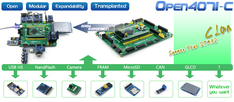
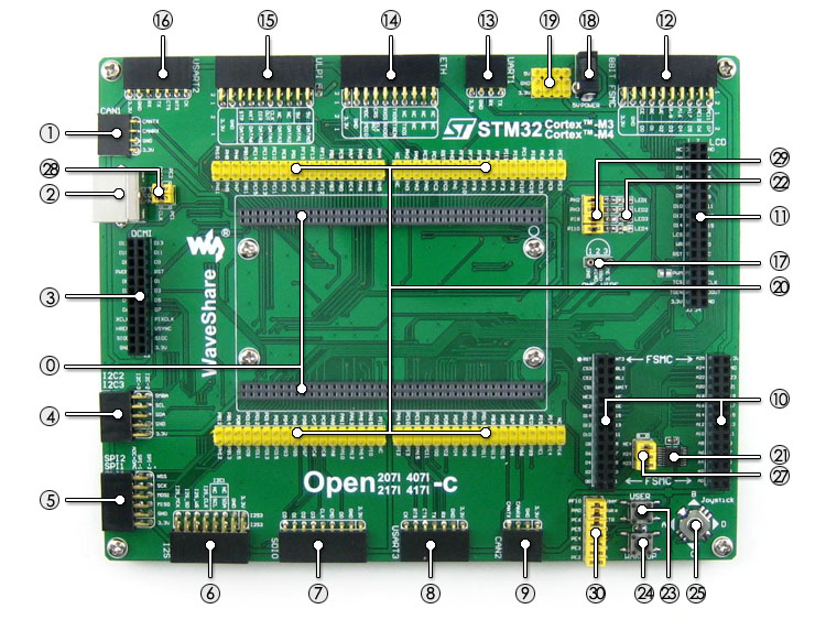
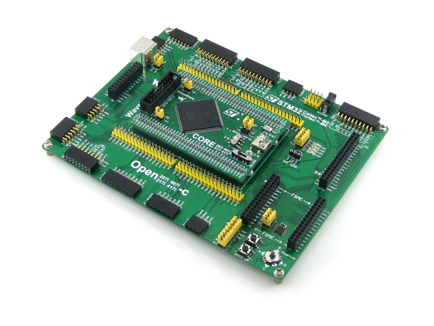
      Open407I-C is an STM32 development board designed for the STM32F407IGT6 microcontroller, consists of the mother board and the MCU core board Core407I.

      The Open407I-C supports further expansion with various optional accessory boards for specific application. The modular and open design makes it the ideal for starting application development with STM32F4 series microcontrollers.
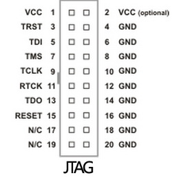
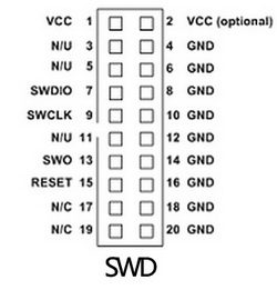

      What's on the mother board

      STM32F407IGT6 development board on board resource

      1. MCU core board connector: for easily connecting the Core407I
      2. CAN1 interface: communicates with accessory boards which feature the CAN device conveniently
      3. PS/2 interface: easily connects to PS/2 keyboard and/or mouse
      4. DCMI interface: for connecting camera module
      5. I2C2 / I2C3 interface: easily connects to I2C peripherals such as I/O expander (PCF8574), EEPROM (AT24Cxx), etc.
      6. SPI1 / SPI2 interface
        • easily connects to SPI peripherals such as DataFlash (AT45DBxx), SD card, MP3 module, etc.
        • SPI1 features AD/DA alternative function, supports connecting AD/DA module as well
      7. I2S2 / I2S3 / I2C1: for connecting I2S peripherals, such as Audio module
      8. SDIO interface: for connecting Micro SD module, features much faster access speed rather than SPI
      9. USART3 interface: easily connects to RS232, RS485, USB TO 232, etc.
      10. CAN2 interface: communicates with accessory boards which feature the CAN device conveniently
      11. 16-bit FSMC interface: easily connects to peripherals such as NorFlash, SRAM, etc.
      12. 16-bit FSMC + SPI interface: for connecting touch screen LCD
      13. 8-bit FSMC interface: easily connects to peripherals such as NandFlash, Ethernet, etc.
      14. UART1 interface: easily connects to RS232, RS485, USB TO 232, etc.
      15. Ethernet interface: easily connects the MCU to ethernet network by using an additional ethernet module
      16. ULPI interface: for connecting high-speed USB peripheral (the STM32F407I integrates USB HS controller without any PHY device)
      17. USART2 interface: easily connects to RS232, RS485, USB TO 232, etc.
      18. ONE-WIRE interface: easily connects to ONE-WIRE devices (TO-92 package), such as temperature sensor (DS18B20), electronic registration number (DS2401), etc.
      19. 5V DC jack
      20. 5V/3.3 V power input/output: usually used as power output, also common-grounding with other user board
      21. MCU pins connector: all the I/O ports are accessible on expansion connectors for further expansion
      22. 74LVC139: used for FSMC expansion, make it possible to connect multi devices through FSMC at the same time, such as LCD and NAND FLASH
      23. LEDs: convenient for indicating I/O status and/or program running state
      24. User key: convenient for I/O input and/or interact with running code
      25. Wake-Up button: wake up the STM32 MCU from sleep mode, also used as regular user key
      26. Joystick: five positions
      27. Crystal empty slot (on bottom side): for soldering 50M active crystal oscillator, which'll provide clock to DCMI
      28. 74LVC139 selection jumper: for FSMC chip select
      29. PS/2 jumper
      30. LEDs jumper
      31. User key / joystick jumper

      For jumpers 27-30:

      • short the jumper to connect to I/Os used in example code
      • open the jumper to connect to other custom pins via jumper wires

      What's on the Core407I

      Core407I on board resource

      1. STM32F407IGT6:the high performance STM32 MCU which features:
        • Core: Cortex-M4 32-bit RISC
        • Feature: a full set of single-cycle DSP instructions
        • Operating Frequency: 168MHz, 210 DMIPS/1.25 DMIPS/MHz
        • Operating Voltage: 1.8V-3.6V
        • Package: LQFP176
        • Memories: 1024kB Flash, 192+4kB SRAM
        • MCU communication Interfaces:
          • 3 x SPI, 4 x USART, 2 x UART, 2 x I2S, 3 x I2C
          • 1 x FSMC, 1 x SDIO, 2 x CAN
          • 1 x USB 2.0 high-speed/full-speed device/host/OTG controller with dedicated DMA, ULPI and on-chip full-speed PHY
          • 1 x 10/100 Ethernet MAC
          • 1 x 8 to 14-bit parallel camera interface
        • AD & DA converters: 3 x AD (12-bit, 1μs, shares 24 channels); 2 x DA (12-bit)
        • Debugging/Programming: supports JTAG/SWD (serial wire debug) interfaces, supports IAP
      2. AMS1117-3.3 (on bottom side), 3.3V voltage regulator
      3. MIC2075 (on bottom side), onboard USB power management device
      4. Power supply switch, powered from 5Vin or USB connection
      5. Boot mode switch, for configuring BOOT0 pin
      6. Power indicator
      7. VBUS LED
      8. Reset button
      9. 8M crystal oscillator (on bottom side)
      10. 32.768K crystal (on bottom side), for internal RTC with calibration
      11. JTAG/SWD interface: for debugging/programming
      12. USB interface
        • as DEVICE, used for establishing USB communication between PC and the STM32 development board
        • as HOST, connecting to USB devices such as USB flash drive through a USB OTG cable
      13. MCU pins expander, VCC, GND and all the I/O ports are accessible on expansion connectors for further expansion
      14. 5Vin pinheader, 5V power supply is required when using USB HOST/OTG
      15. USB HOST/OTG jumper
        • short the jumper when using USB HOST/OTG
        • open the jumper to disconnect from I/O port
      16. VBAT selection jumper
        • short the jumper to use system power supply
        • open the jumper to connect the VBAT to external power, such as battery
      17. VREF selection jumper
        • short the jumper to connect VREF+ to VCC
        • open the jumper to connect VREF+ to other custom pin via jumper wire

      Package Content

      1. Open407I-C development board x 1
      2. PL2303 USB UART Board (mini) x 1
      3. USB type A plug to mini-B plug cable x 1
      4. USB type A receptacle to mini-B plug cable x 1
      5. 4-pin wire x 2
      6. 2-pin wire x 2
      7. USB power cable x 1
      8. Software CD x 1

      Note:
      The Open407I-C supports programming via STM32 UART bootloader, a USB TO UART accessory board is also provided in the package.
      The Open407I-C does NOT integrate any debugging function, a debugger is required.


      JTAG/SWD interfaces

      The figure 1, and 2 show the header pinouts of JTAG/SWD interface


      JTAG Header Pinout

      SWD Header Pinout

      Development Resources

      • Related software (KEIL etc.)
      • Demo code (examples in C, μC/OS-II)
      • Schematic (PDF)
      • STM32 development documentations (Datasheet etc.)

      Wiki: www.waveshare.com/wiki/Open407I-C

      Waveshare Electronics
      WS-6485

      Špecifické referencie

      Open407I-C Standard, STM32F4 Development Board (WS-6485) for STM32F407 IGT6

      Open407I-C Standard, STM32F4 Development Board (WS-6485) for STM32F407 IGT6