

RLX COMPONENTS s.r.o. , Electronic Components Distributor.
RLX COMPONENTS s.r.o. , Electronic Components Distributor.
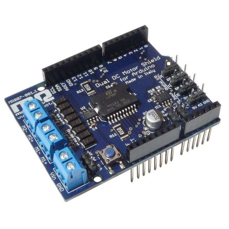
Dual DC Motor Shield (MR007-001.1)
The Dual DC Motor Shield is a shield that has been projected to enable an Arduino board to drive two brushed DC motors or one 4-wire two-phase stepper motor, controlling the speed and direction of each one independently.
Some applications may need to control the motor speed or a servo angular position by a potentiometer; for these reasons in this shield two digital I/O ports and two analog input ports have been added.
Analog input ports can be used to read potentiometers or any other analogic sensor, while digital I/O ports can be used to drive servos or interface other digital devices.
This shield is based on the L298, a high voltage, high current dual full-bridge driver. To prevent board damages, all driver lines are diode protected from back EMF. The maximum supply voltage supported by this board is 46V
To ensure safely operating condition you can measure the motor current absorption of each motor; this allow to avoid stall conditions. On this shield it has been included an integrated I2C digital temperature sensor to monitor the shield temperature in order to prevent overtemperature threat.
In fact when the L298 chip works at high current values it may become very hot and this heat can flow through all the shield. To avoid dangerous overheating condition you can use the integrated I2C digital temperature sensor mounted close to the L298 chip. This allows the temperature monitoring via the I2C bus using the Arduino pins SCL and SDA. The sensor is the integrated circuit TCN75A and you can refer to its datasheet to better understanding its communication protocol.
The logic of the Dual DC Motor Shield is powered directly from the Arduino board, whereas motor outputs can be powered both from Arduino Vin pin or from external power source, even if it is strongly encouraged to use external power supply.
On this shield the selection of the power source for motor outputs is accomplished by a jumper. Moving the jumper from one side to the other the power source can be changed.
This board also provides direction LED indicators for both channels and this is very usefull during setup stage to verify the firmware behaviour; the led indicators work also without appling a real motor to the output.