ST-LINK/V2 (CN), STM Programmers & Debuggers (WS-5822)
      ST-LINK/V2 (CN), STM Programmers & Debuggers (WS-5822)

      ST-LINK/V2 (CN), STM Programmers & Debuggers (WS-5822)

      WS-5822

      ST-LINK/V2 (CN), STM Programmers & Debuggers (WS-5822)

      Množstvo:

      ST-LINK/V2 (CN), STM Programmers & Debuggers (WS-5822)

      DESCRIPTION

      ST-LINK/V2, in-circuit debugger/programmer for STM8 and STM32

      ST-LINK/V2 image

      Description

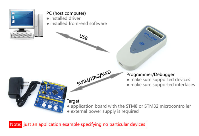
      The ST-LINK/V2 is an in-circuit debugger and programmer for the STM8 and STM32 microcontroller families. The single wire interface module (SWIM) and JTAG/serial wire debugging (SWD) interfaces are used to communicate with any STM8 or STM32 microcontroller located on an application board.

      STM8 applications use the USB full speed interface to communicate with STMicroelectronic's ST Visual Develop (STVD) or ST Visual Program (STVP) software.

      STM32 applications use the USB full speed interface to communicate with Atollic, IAR, Keil or TASKING integrated development environments.

      Key Features

      • 5 V power supplied by a USB connector
      • USB 2.0 full speed compatible interface
      • USB standard A to mini B cable
      • SWIM specific features
        • 1.65 V to 5.5 V application voltage supported on SWIM interface
        • SWIM low-speed and high-speed modes supported
        • SWIM programming speed rate: 9.7 Kbytes/s in low speed and 12.8 Kbytes/s in high speed
        • SWIM cable for connection to the application via an ERNI standard vertical (ref: 284697 or 214017) or horizontal (ref: 214012) connector
        • SWIM cable for connection to the application via a pin header or a 2.54 mm pitch connector
      • JTAG specific features
        • 1.65 V to 3.6 V application voltage supported on the JTAG interface and 5 V tolerant inputs
        • JTAG cable for connection to a standard JTAG 20-pin pitch 2.54 mm connector
      • Direct firmware update feature supported (DFU)
      • Status LED which blinks during communication with the PC
      • Operating temperature 0 to 50 °C

      Photos

      ST-LINK/V2 Back View
      ST-LINK/V2 Back View
      ST-LINK/V2 Cables
      Cables comes with ST-LINK/V2

      Application Example

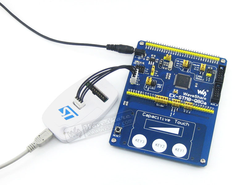
      Connecting the PC and STM8/STM32 application board through ST-LINK/V2 to establish hardware connection:

      ST-LINK/V2 application example

      Supported Devices

      Microcontrollers supported by STVP release 3.2.8:

      Product lineMicrocontroller
      STM32 STM32F100xx, STM32F101xx, STM32F102xx, STM32F103xx, STM32F105xx, STM32F107xx, STM32F2xxx, STM32F4xxx,

      STM32L15xx6, STM32L15xx8,STM32L15xxB, STM32L151xC, STM32L151xD, STM32L152xC, STM32L152xD, STM32L162xD,

      STM32TS60,

      STM32W108C8, STM32W108xB, STM32W108xC, STM32W108xZ
      STM8 STM8AF51x, STM8AF52x, STM8AF61x, STM8AF62x,STM8AH51x, STM8AH61x, 

      STM8S003K3, STM8S003F3, STM8S005C6, STM8S005K6, STM8S007C8, STM8S103xx, STM8S105xx, STM8S207xx, STM8S208xx, STM8S903F3, STM8S903K3, 

      STM8L101xx, STM8L15x, STM8L16x,

      STM8TL52x4,STM8TL53x4

      SW DRIVERS

      While connecting the ST-LINK/V2 to the computer through USB interface, the USB driver is required and should be installed correctly first.

      Click on the link below to download:

      ST-LINK/V2 USB driver for Windows 7, Vista and XP


      Connection with STM8 applications

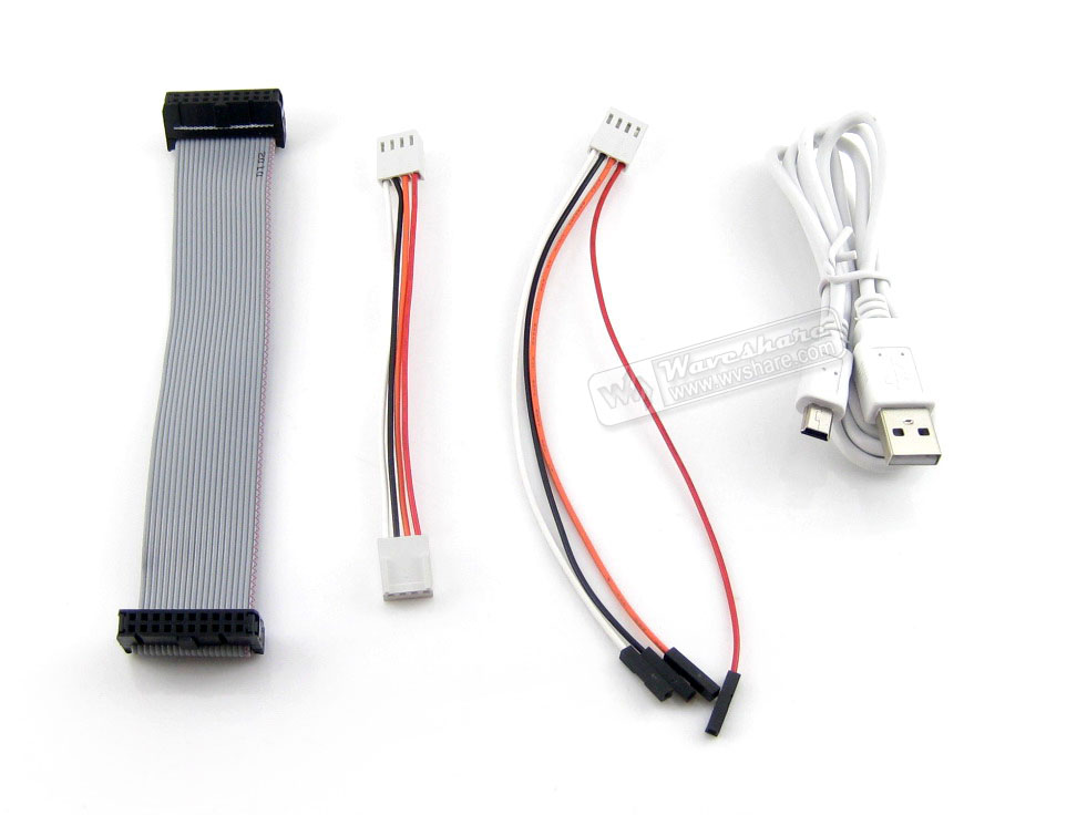
      The ST-LINK/V2 should be connected to the STM8 application via the SWIM cable. Two SWIM cables are delivered with the product:

      • SWIM flat ribbon with a standard ERNI connector at one end and a 4-pin connector at the other end
      • SWIM flat ribbon ended with a 4-pin, 2.54 mm, low-cost connector on two sides

      Figure 1. ST-LINK/V2 SWIM header pinout

      Figure 2. Connecting with STM8 application board

      Connection with STM32 applications

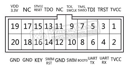
      For STM32 developments the ST-LINK/V2 must be connected to the application using the standard 20-pin female-female JTAG flat ribbon provided.

      Debugging connector layout
      Figure 3. Debugging connector layout on ST-LINK/V2 and flat cable
      connection with STM32 application
      Figure 4. Connecting with STM32 application board

      ST-LINK/V2 Status

      The LED labeled 'COM' on top of the ST-LINK/V2 shows the ST-LINK/V2 status (whatever the connection type). When the:

      • LED is blinking RED: the first USB enumeration with the PC is taking place. If it keeps blinking RED, maybe the USB driver is NOT found.
      • LED is RED: communication between ST-LINK/V2 and the PC is established (end of enumeration).
      • LED is blinking GREEN/RED: data are being exchanged between the target and the PC.
      • LED is GREEN: the last communication has been successful.
      • LED is ORANGE: ST-LINK/V2 communication with the target has failed.

      Downloads

      Development resources:user manual, driver, software, etc.
      Wiki: www.waveshare.com/wiki/ST-LINK/V2_(CN)

      Package Contains

      1. ST-LINK/V2 × 1
      2. USB type A to Mini-B cable × 1
      3. 20-pin JTAG/SWD flat ribbon × 1
      4. 4-pin SWIM cable × 1
      5. 4-pin SWIM custom connector cable × 1

      Waveshare Electronics
      WS-5822

      Špecifické referencie

      upc
      700646949694
      ST-LINK/V2 (CN), STM Programmers & Debuggers (WS-5822)

      ST-LINK/V2 (CN), STM Programmers & Debuggers (WS-5822)