1-Wire to I2C Raspberry Pi accessory boards")
 1-Wire to I2C Raspberry Pi accessory boards")
 1-Wire to I2C Raspberry Pi accessory boards")
 1-Wire to I2C Raspberry Pi accessory boards")
 1-Wire to I2C Raspberry Pi accessory boards")
RLX COMPONENTS s.r.o. , Electronic Components Distributor.
RLX COMPONENTS s.r.o. , Electronic Components Distributor.
")
1 Wire Pi Zero (AB Electronics UK) 1-Wire to I2C Raspberry Pi accessory boards
1 Wire Pi Zero (AB Electronics UK) 1-Wire to I2C Raspberry Pi accessory boards
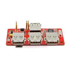
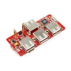
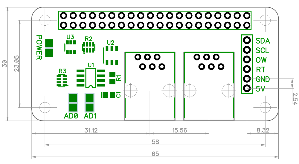
The 1 Wire Pi Zero from AB Electronics UK is a communication board supporting the 1-Wire® protocol designed for use on the Raspberry Pi Zero. A 5V buffered I2C port is also provided on the board. The 1 Wire Pi Zero can be securely fitted to your Raspberry Pi using our mounting kit pack.
The 1-Wire® port on the 1 Wire Pi Zero is based around a DS2482-100 I2C to 1-Wire® bridge device. The DS2482-100 provides bi-directional protocol conversion between the I2C port on the Raspberry Pi and any attached 1-Wire® slave devices. An ESD Protection Diode is used to protect the 1 Wire Pi Zero and Raspberry Pi from electrostatic spikes on the 1-Wire® port. Connections to the 1-Wire® port can be made through the RJ-12 socket or the solder points on the PCB. We have a knowledge base article for configuring and using the 1-Wire® port on your Raspberry Pi.
The 1 Wire Pi Zero is powered through the host Raspberry Pi using the GPIO port and extended pins on the GPIO connector allow you to stack the 1 Wire Pi Zero along with other expansion boards.
A 5V input port is also provided allowing you to use an external power supply on the 1-Wire® interface, reducing the load on the Raspberry Pi. If you choose to use the external 5V input please remove the solder jumper on the board to isolate the Raspberry Pi 5V bus.
A detailed tutorial has been written by Jack Creasey, author of Raspberry Pi Essentials,for the setup of OWFS with the 1 Wire Pi and 1 Wire Plus boards. View the tutorial.
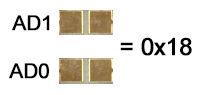
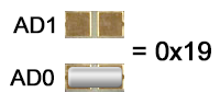
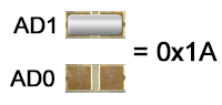
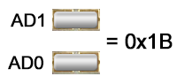
The 1 Wire Pi Zero includes two address selection solder jumpers which can be bridged with solder to give you up to 4 different I2C addresses.
Configuration 1:
Configuration 2:
Configuration 3:
Configuration 4:
| Model | Status |
|---|---|
| Raspberry Pi Model A | No |
| Raspberry Pi Model B | No |
| Raspberry Pi 1 Model A+ | Yes |
| Raspberry Pi 1 Model B+ | Yes |
| Raspberry Pi 2 Model B | Yes |
| Raspberry Pi 3 Model B | Yes |
| Raspberry Pi Zero | Yes |
| Raspberry Pi Zero W | Yes |
| Orange Pi | Yes |
| Asus Tinker Board | Yes |
| Odroid | Yes |
Vdd (5V input pin): 5.0V
Maximum current on 1-Wire pins: ±20 mA
I2C SDA/SCL voltage: 5.0 V
I2C port current: 100 mA
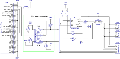
Click to download schematic PDF.
The 1 Wire Pi Zero is supplied with the 40 pin GPIO connector, RJ12 connector and 2 pin jumper unsoldered.
Before using the 1 Wire Pi Zero you will need to solder the two connectors onto the PCB. We suggest soldering the 40 pin GPIO connector first and then the RJ12 connector. The RJ12 connector is supplied clipped onto the PCB.
Download and print our PCB Header Assembly Jig to hold your circuit board when soldering the header pins.
![]()
The 1-Wire® port on the 1-Wire Pi can be accessed through the female RJ12 socket or the solder points on the PCB. An ESD protection diode is fitted between the RJ12 port and the 1-Wire® interface IC.
The pinout connections for the RJ12 port are shown below:
Pin Usage
1 5V
2 Ground
3 OW (1-Wire® Data, ESD Protected)
4 RT (1-Wire® Return/Ground, ESD Protected)
5 NC
6 NC
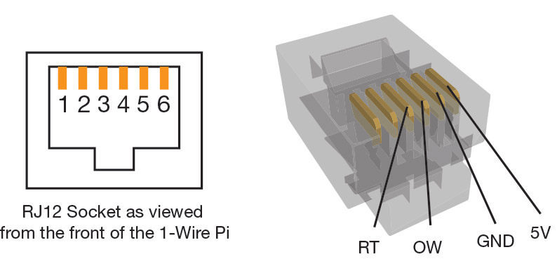
Click image to enlarge
The Quick2wire lib from https://github.com/quick2wire/quick2wire-python-api allows easy access to the I2C port via Python.
Špecifické referencie
2.95 € bez DPH
1 Wire Pi Zero (AB Electronics UK) 1-Wire to I2C Raspberry Pi accessory boards