

 16-channel, 12-bit PWM controller for the Raspberry Pi")
 16-channel, 12-bit PWM controller for the Raspberry Pi")
 16-channel, 12-bit PWM controller for the Raspberry Pi")
 16-channel, 12-bit PWM controller for the Raspberry Pi")
RLX COMPONENTS s.r.o. , Electronic Components Distributor.
RLX COMPONENTS s.r.o. , Electronic Components Distributor.
")
Servo PWM Pi Zero (AB Electronics UK) 16-channel, 12-bit PWM controller for the Raspberry Pi
Servo PWM Pi Zero (AB Electronics UK) 16-channel, 12-bit PWM controller for the Raspberry Pi
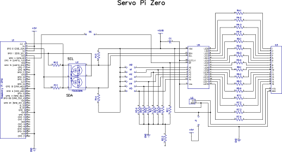
The Servo PWM Pi Zero is a 16-channel, 12-bit PWM controller for the Raspberry Pi, suitable for driving LEDs and radio control servos. The board is based around PCA9685 PWM I2C LED controller IC from NXT and can drive each of the 16 outputs with 12 bit (4096 steps) duty cycle from 0% to 100%.
The output frequency is programmable from a typical 40Hz to 1000Hz. Each output driver is programmed to be either open-drain with a 22 mA current sink capability at 5 V or totem pole with a 22 mA sink, 10 mA source capability at 5 V. 220R current limiting resistors are used on each channel allowing you to connect servos or LEDs directly to the outputs.
The PCA9685 contains 5 I2C address selection pins which can be configured using solder bridges on the Servo PWM Pi Zero PCB. Using different I2C addresses on your Servo Pi allows you to stack several boards on a single Raspberry Pi, see the data-sheet for more details on I2C address selection. The active LOW Output Enable input pin (OE) on the PCA9685 allows asynchronous control of the LED outputs and can be used to set all the outputs to a defined I2C-bus programmable logic state. The OE can also be used to externally ‘pulse width modulate’ the outputs, which is useful when multiple devices need to be dimmed or blinked together using software control. The OE pin can be connected to pin 7 (GPIO 4) on the Raspberry Pi GPIO port by bridging the solder pads on the Servo Pi marked OE.
The Servo Pi is only compatible with analogue RC servos, digital servos will not work. While the Servo Pi uses a 12 bit (4096 step) controller due to the way RC servos are designed only approximately 200 steps will be available for controlling the servo. You can find an example python library for controlling an RC servo at https://github.com/abelectronicsuk/ABElectronics_Python_Libraries/tree/master/ServoPi
For safety reasons the Servo PWM Pi Zero is not connected to the 5V power rail on the Raspberry Pi.
Due to the high currents used on radio control servos and other PWM devices it is recommended that you use an external 5V power supply to power the Servo Pi. External power can be provided through the 5V and GND pads on the Servo PWM Pi Zero. If you use two power supplies, one for the Raspberry Pi and one for the Servo Pi please ensure that the ground wires on the two supplies are joined and do not have any potential difference between them. Any potential difference between the grounds could damage the Raspberry Pi and yourself.
If you are using the Servo PWM Pi Zero for low current applications, below 300mA, you can power the Servo PWM Pi Zero through the 5V pins on the Raspberry Pi GPIO port by bridging the “PWR Link” pads with a blob of solder.
Bridging the “PWR Link” pads will also allow you to power your Raspberry Pi from the Servo Pi power pins using an external 5V power supply but please note this will bypass the internal fuse on the Raspberry Pi leaving it vulnerable to damage from short circuits on any of the GPIO pins.
Servo Pi Zero Address Selection
| Model | Status |
|---|---|
| Raspberry Pi Model A | No |
| Raspberry Pi Model B | No |
| Raspberry Pi 1 Model A+ | Yes |
| Raspberry Pi 1 Model B+ | Yes |
| Raspberry Pi 2 Model B | Yes |
| Raspberry Pi 3 Model B | Yes |
| Raspberry Pi Zero | Yes |
| Raspberry Pi Zero W | Yes |
| ODroid C1 | Yes |
| ODroid C2 | Yes |
Maximum input voltage: 5.5V when PWR Link is not bridged.
Maximum current on each PWM pin 22mA
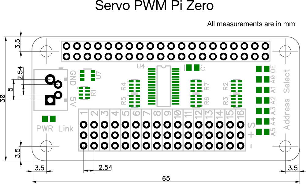
The Servo PWM Pi Zero is supplied with the 40 pin GPIO connector unsoldered.
We supply the Servo PWM Pi Zero this way because the Raspberry Pi Zero is also supplied without a GPIO header and the Servo PWM Pi Zero could therefore be fitted both above or below the Raspberry Pi Zero.
Before using the Servo PWM Pi Zero you will need to solder the 40 pin GPIO connectors onto the PCB.
Download and print our PCB Header Assembly Jig to hold your circuit board when soldering the header pins.
Click image to enlarge
We have Python, Arduino, C, C++, Node.js and Windows 10 IOT libraries available for this expansion board. You can download all of the libraries from github at:
https://github.com/abelectronicsuk/ or click on the logos below for your selected programming language
Špecifické referencie
Servo PWM Pi Zero (AB Electronics UK) 16-channel, 12-bit PWM controller for the Raspberry Pi