




RLX COMPONENTS s.r.o. , Electronic Components Distributor.
RLX COMPONENTS s.r.o. , Electronic Components Distributor.

18.70 € bez DPH
4.3inch ESP32-S3 Touch Display , 480x272 | Resisitive Touch, With WiFi and BLE (ER-DLE05943B)
4.3inch ESP32-S3 Touch Display , 480x272 | Resisitive Touch, With WiFi and BLE (ER-DLE05943B)
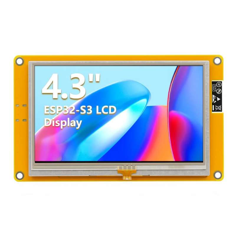
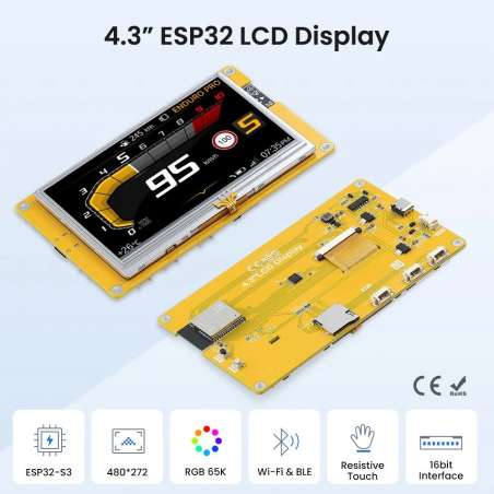
Táto 4,3-palcová vývojová doska s displejom ESP32-S3 dokonale kombinuje vysokovýkonný dvojjadrový procesor ESP32-S3 s farebným displejom s rozlíšením 480x272. Hlavný radič využíva dvojjadrový procesor Xtensa LX7 s taktovacou frekvenciou až 240 MHz a obsahuje 8 MB PSRAM a 16 MB flash pamäte. Podporuje bezdrôtovú komunikáciu Wi-Fi 2,4 GHz a Bluetooth 5.0, čím poskytuje dostatočný výpočtový výkon a rozširovateľnosť pre aplikácie IoT a vstavané HMI. Obrazovka je 4,3-palcový farebný TN displej, ktorý podporuje farebné zobrazenie RGB565 a rezistívny dotyk, čím ponúka sýte farby a pohodlnú interakciu človek-stroj. Doska je vybavená rozhraním Type-C, slotom pre Micro TF kartu, sériovým portom, SPI, UART a ďalšími rozširujúcimi rozhraniami, s dostatočným počtom GPIO pinov pre jednoduché pripojenie k rôznym perifériám. Poskytuje kompletnú sadu vzorových programov a podporu ovládačov na nízkej úrovni. Produkt prešiel prísnymi testami starnutia a podporuje dlhodobú stabilnú prevádzku, čo z neho robí ideálnu voľbu pre centrálne ovládanie inteligentnej domácnosti, priemyselné ovládacie terminály, uzly IoT a ďalšie projekty.


Hardware Overview


|
Interface Name |
Function Description |
|
① ESP32-S3 |
Display module main control, control board peripheral and external peripheral. |
|
② MicroSD card slot |
A MicroSD card is inserted to expand the storage space for storing large data such as characters, pictures, and audio files. |
|
③UART0 |
1.25mm 4P connector.It can be used for serial debugging, downloading, and communication. An external USB to serial port module is required. |
|
④ BOOT Key |
Used to enter download mode or key test. Press and hold this button to power on and release it to enter the download mode. Alternatively, press and hold this button and then press the RESET button to release the RESET button and then release this button to enter the download mode. When you do not need to enter the download mode, this button can be used as a common button. |
|
⑤ Type-C Interface |
Used for module power supply and download programs. This interface is connected to the one-click download circuit on the module, which can automatically enter the download mode (without pressing the BOOT key). |
|
⑥ RESET Key |
Used for ESP32 master control and LCD reset, level reset after pressing. |
|
⑦ Expand Pin |
1.25mm 4P socket, leading out GPIO17/GPIO18 pins. |
|
⑧ UART1 & USB |
1.25mm 4P socket, leading out four free pins: GPIO17, GPIO18, GPIO19 and GPIO20. GPIO17 and GPIO18 can be used for UART1, while GPIO19 and GPIO20 are compatible with the USB protocol. |
|
⑨ SPI Interface |
1.25mm 4P socket, designed for connecting external SPI communication devices. This SPI interface is shared with the resistive touch screen and SD card, and can also be used as GPIO. |
|
ESP32 Module |
|
|
Chip |
ESP32-S3 (N16R8) |
|
CPU |
Xtensa LX7 32-bit dual-core processor |
|
Frequency |
240MHz(Max) |
|
Memory |
384KB ROM+512KB SRAM+16KB RTC SRAM+8M internal OPI PSRAM+16M external SPI Flash |
|
Wi-Fi |
2.4GHz, 802.11b/g/n mode |
|
Bluetooth |
Bluetooth V5.0 BR/EDR and Bluetooth LE standard |
|
Screen |
|
|
Panel Size |
4.3 inch |
|
Panel Type |
TN TFT |
|
Touch Screen Type |
Resistive touch screen |
|
Resolution |
480x272 |
|
Active Area |
95.04(W)x53.86(H)(mm) |
|
Number of Pixels |
65K(RGB565) |
|
Display Driver IC |
ILI6485 |
|
Screen interface |
RGB565-16Bit |
|
View Angle |
6 ’CLOCK |
|
Brightness(TYP) |
350 cd/m2 |
|
Backlight Type |
White LED*7 |
|
Touch Driver IC |
XPT2046 |
|
Communication Interface |
SPI |
|
Pixel Size |
0.153(H)x0.153(mm) |
|
Other |
|
|
Working Voltage |
5.0V |
|
Total current (typical value) |
190mA |
|
Total power consumption (typical value) |
0.95W |
|
Operation Temperature |
-20~60(℃) |
|
Storage temperature |
-30~70(℃) |
|
Module Size |
123(W)x74(H)x8.7(D) |
|
Net Weight |
95g |
|
Onboard Equipment |
ESP32 Connect Pins |
Pin Description of Onboard Equipment |
|
LCD |
IO40 |
Data Enable Control Pin |
|
IO41 |
Vertical Sync Signal Control Pin |
|
|
IO39 |
Horizontal Sync Signal Control Pin |
|
|
IO42 |
Pixel Clock Control Pin |
|
|
IO42/48/47/21/14 |
5-bit RED Data Pin |
|
|
IO5/6/7/15/16/4 |
6-bit GREEN Data Pin |
|
|
IO8/3/46/9/1 |
5-bit BLUE Data Pin |
|
|
RTP |
IO12 |
Resistive Touch Screen SPI Bus Clock Control Pin |
|
IO13 |
Resistive Touch Screen SPI Bus Data Write Control Pin |
|
|
IO11 |
Resistive Touch Screen SPI Bus Data Read Control Pin |
|
|
IO38 |
Resistive Touch Screen SPI Bus Chip Select Control Pin |
|
|
IO18 |
Resistive Touch Screen SPI Bus Interrupt Control Pin |
|
|
MicroSD |
IO10 |
SD Card SPI Bus Chip Select Control Pin |
|
IO11 |
SD Card SPI Bus Data Read Control Pin |
|
|
IO13 |
SD Card SPI Bus Data Write Control Pin |
|
|
IO12 |
SD Card SPI Bus Clock Control Pin |
|
|
KEY |
IO0 |
Download Mode Selection Button (Press this button to power on, then release to enter download mode) |
|
EN |
ESP32-S3 Reset Button, Active Low Reset |
|
|
UART0 |
RXD0(IO43) |
ESP32-S3 UART0 Transmit Signal Pin |
|
TXD0(IO44) |
ESP32-S3 UART0 Receive Signal Pin |
|
|
SPI |
IO19 |
SPI Bus Chip Select Control Pin |
|
IO11 |
SPI Bus Data Read Control Pin |
|
|
IO13 |
SPI Bus Data Write Control Pin |
|
|
IO12 |
SPI Bus Clock Control Pin |
|
|
Expand pin |
IO18 |
It can be used as GPIO when the touch and SD card functions are not in use. |
|
IO17 |
It can be used as GPIO when the touch and SD card functions are not in use. |
|
|
USB |
IO19 |
USB Bus Differential Signal Data Line (Negative) |
|
IO20 |
USB Bus Differential Signal Data Line (Positive) |
|
|
UART1 |
IO17 |
ESP32-S3 UART1 Transmit Signal Pin |
|
IO18 |
ESP32-S3 UART1 Receive Signal Pin |
Špecifické referencie
4.3inch ESP32-S3 Touch Display , 480x272 | Resisitive Touch, With WiFi and BLE (ER-DLE05943B)
18.70 € bez DPH