

RLX COMPONENTS s.r.o. , Electronic Components Distributor.
RLX COMPONENTS s.r.o. , Electronic Components Distributor.
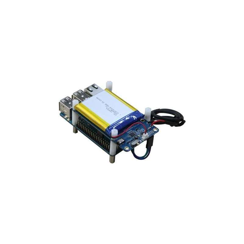
UPS2 for C1/C1+ (Hardkernel) 3000mAh Lithium Polymer battery
The UPS2 for C1 is designed specifically for the ODROID-C1/C1+
Uninterrupted Power Supply is an electrical apparatus that provides emergency power to a load when the input power source, typically mains power, fails. The on-battery runtime of most uninterruptible power sources is relatively short but sufficient to start a standby power source or properly shut down the ODROID-C1/C1+
It is equipped with a rechargeable 3,000mAh Lithium Polymer battery and a charger with a booster IC for 5V output.
When the AC power source fails, the UPS2 keeps supplying the power to the ODROID-C1/C1+ with the battery. There is a digital output pin to notice the battery low-level warning to the ODROID-C1/C1+ to trigger the shutdown process. And the AC power source available, UPS2 will supply the power to the ODROID-C1/C1+ again automatically. It will significantly reduce the risk of data loss by sudden power-down.
Full guide, schematics, PCB layout file and detail information is in our WiKi : http://odroid.com/dokuwiki/doku.php?id=en:odroid-ups2
PACKAGE INCLUDES :
- 3000mAh battery pack
- DC Plug Cable soldered UPS2 board
- 3pin jumper wire (11mm)
- 4 x 20mm PCB spacers (Plastic)
- 4 x 11mm PCB spacers (Metal)
- 4 x 10mm PCB spacers (Plastic)
- 5V/2A Power Supply
JUMPER IT WITH ODROID-C1 :
The AC_OK signal is connected to PIN#11(GPIO #88) in the 40pin header(J2) of ODROID-C1.
The BAT_OK signal is connected to PIN#13(GPIO #116).
The POWER_LATCH signal is connected to PIN#15(GPIO #115).
If you connect it wrong way, you might burn your ODROID-C1 !
| DC Input Voltage / Current | DC 4.8V ~ 5.4V / 2A minimum |
| Battery Charging Time / Current | 1.5 ~ 2 Hours / 2A maximum |
| DC Output Current / Voltage | Maximum 2A / 5V |
| Battery | 3,000mAh Lithium Polymer Connector : Molex 51021-0200 |
| Battery Life Cycle | Carry out 400 cycle charging / discharging @ 20±5℃ |
| Integrated Protection PCB | Over charge and discharge protection |
| Estimated Running Time | 2-4 hours with typical load of 300mA @ 5V |